Tread thickness measuring method

a technology of tread thickness and measuring method, which is applied in vehicle tyre testing, instruments, transportation and packaging, etc., can solve the problems of change in magnetic flux in the detection coil, and achieve the effect of reducing the work efficiency of tire retreading and increasing man-hours

Active Publication Date: 2016-12-06
BRIDGESTONE CORP
View PDF11 Cites 0 Cited by
  • Summary
  • Abstract
  • Description
  • Claims
  • Application Information

AI Technical Summary

Benefits of technology

[0006]However, the eddy-current, sensor needs to create an eddy current in the belt in order to measure the tread thickness. As such, if the belts used in a tire are not steel belts made of steel cords, then the eddy-current sensor will be useless in measuring the tread thickness. That is, if the belts are fiber belts made of fiber cords of organic fiber or other non-metallic material, then, without the induction, of a magnetic flux in the belt, it will be impossible to measure the distance from the tread surface to the outermost belt. Thus, when the belts used in the tire are fiber belts, the worker needs to drill small holes at a plurality of circumferential and axial positions of the tire from the tread surface until the surface of the outermost belt is exposed. Then the worker measures the depth from the tread surface to the outermost belt surface by applying a depth gauge and determines the depth for buffing operation. This will increase the man-hours for buffing and decrease the work efficiency of tire retreading.
[0007]Also, there are cases where the tires employ a fiber belt only for the outermost belt of the belt layer. Retreading such tires is done by first measuring with an eddy-current sensor the depth to the surface of the belt made of steel cords. Then the fiber belt, together with the tread, is abraded by buffing, and a new fiber belt, replacing the fiber belt removed by buffing, is incorporated into the tread to be applied afresh. However, in the fabrication of a tread to be newly bonded to the bonding surface, the tread incorporating the fiber belt entails an increased cost in manufacturing and even raises the retreading cost as a whole.

Problems solved by technology

This will cause a change in the magnetic flux in the detection coil.

Method used


Image

  • Tread thickness measuring method
  • Tread thickness measuring method
  • Tread thickness measuring method

Examples


Embodiment Construction

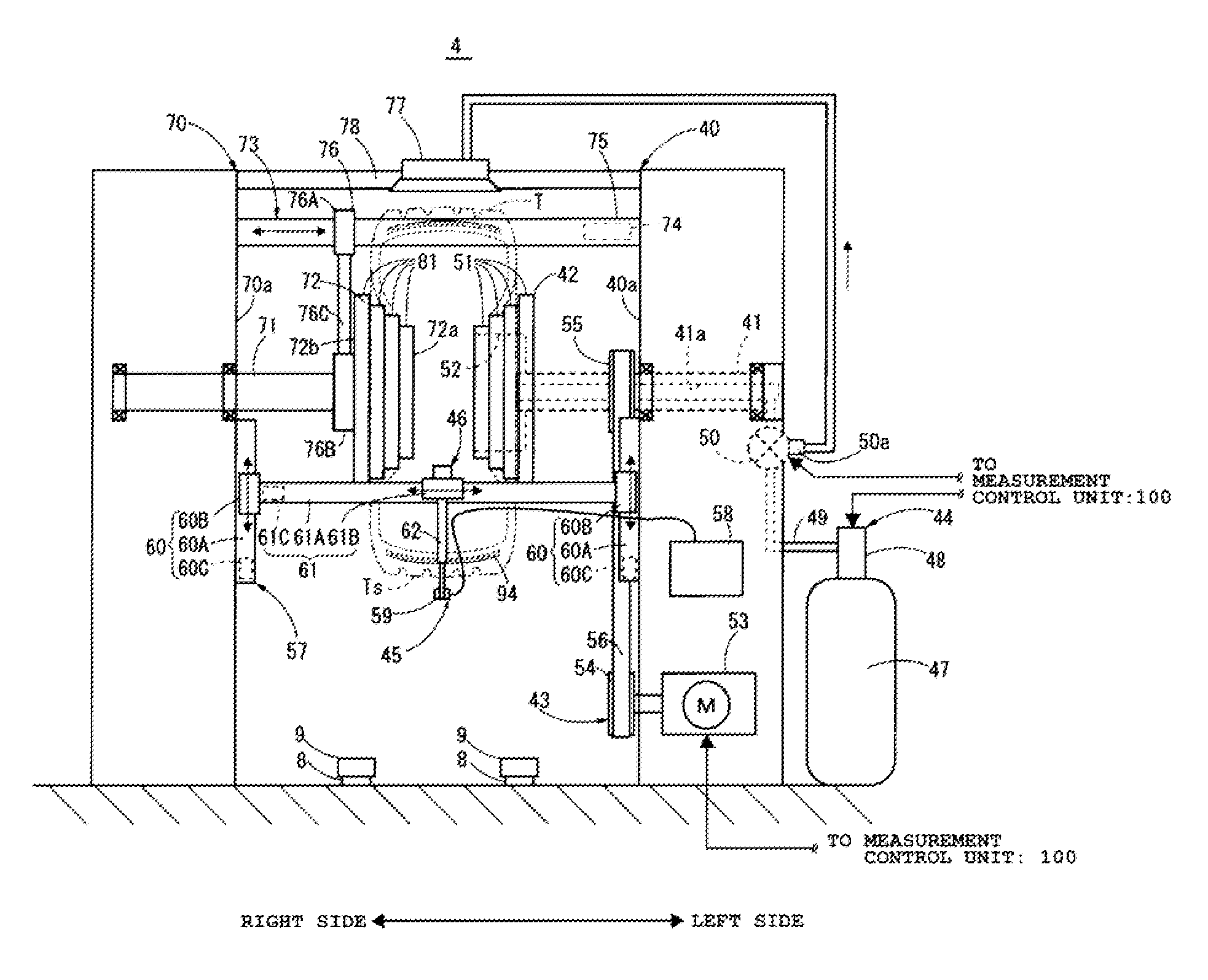
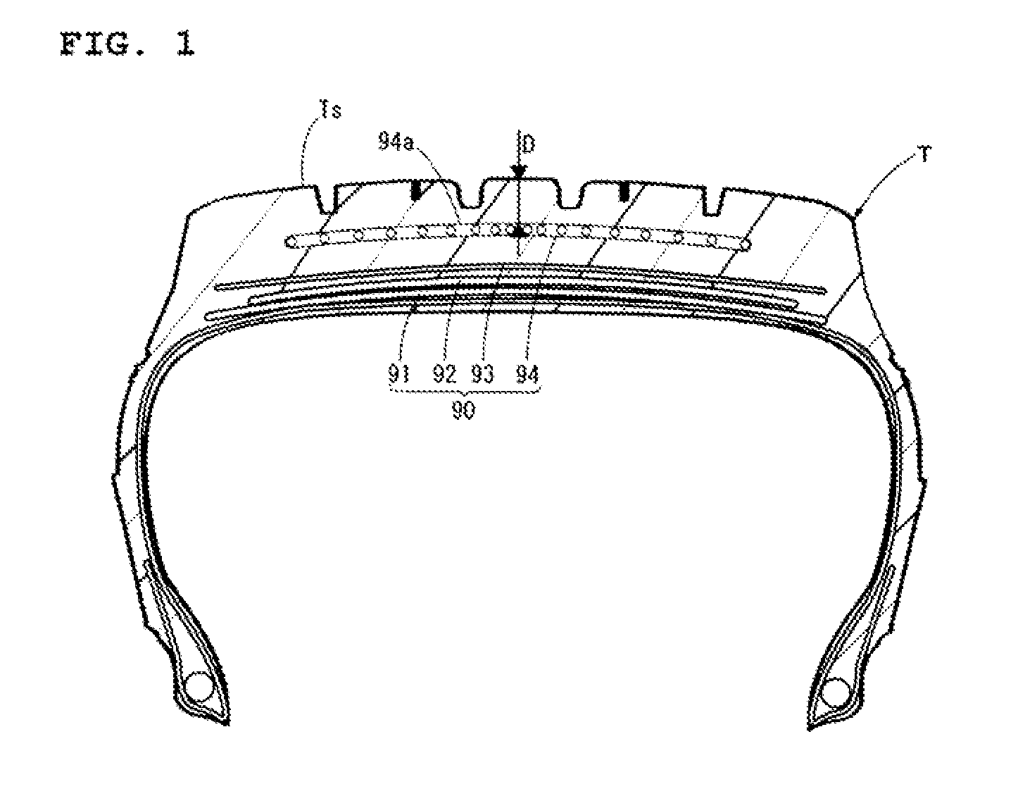
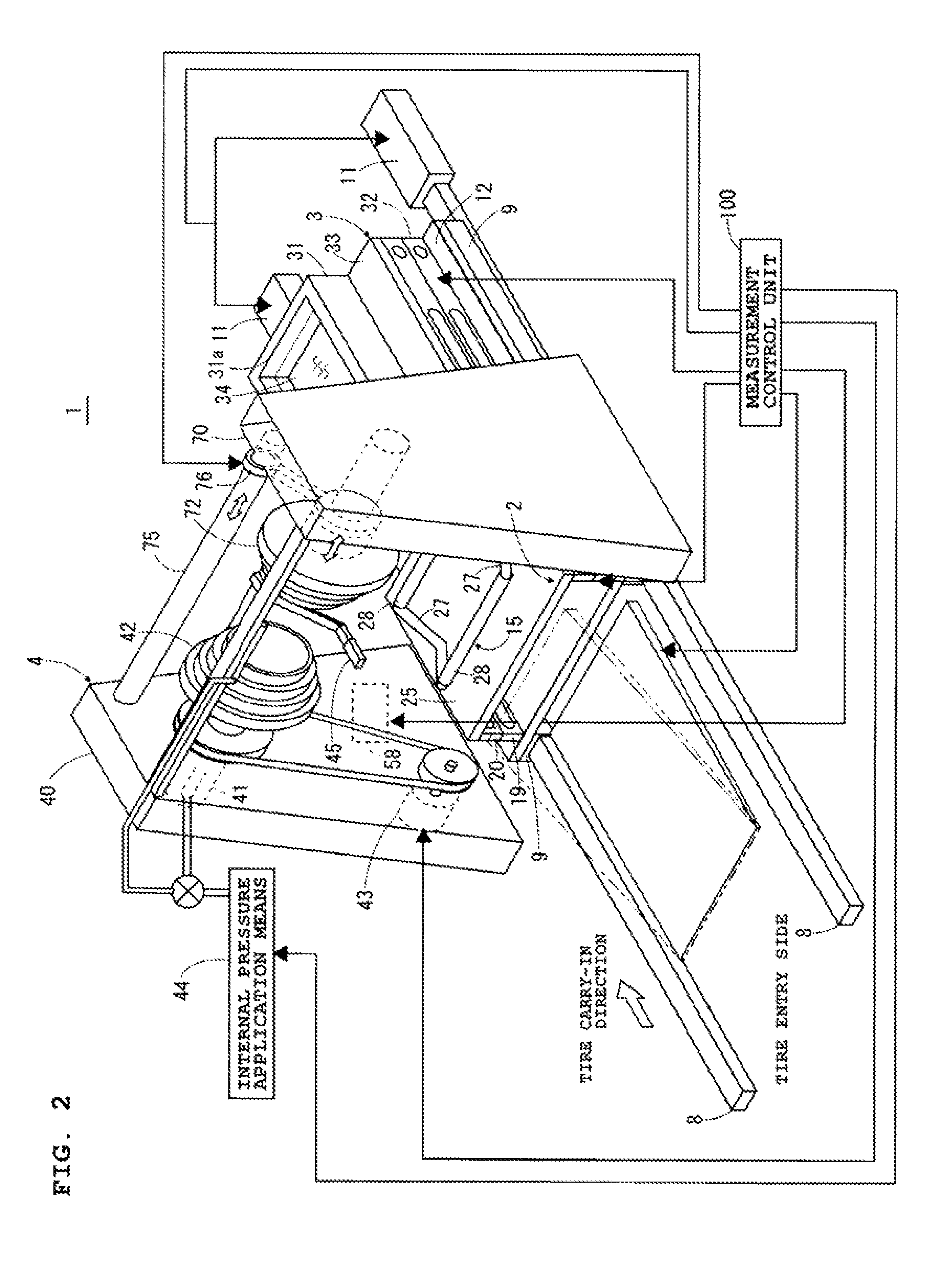
[0027]FIG. 1 is a cross-sectional view of a tire T which is a sample under inspection. FIG. 2 is a structural illustration of a tread thickness measuring apparatus 1.

[0028]A description is first given of the structure of a tire T of which the tread thickness D is measured with a tread thickness measuring apparatus 1 according to the present invention. The tire T, which is a sample under inspection, is a used tire, for instance. And, as shown in FIG. 1, the tire T has a belt layer 90, consisting of a plurality of belts 91 to 94, in the tread region. The belt layer 90 is constituted by the belts 91 to 93, which are located in radially inner positions of the tire, and the belt 94, which is located in a radially outermost position of the tire. The belts 91 to 93 are steel belts made of steel cords, whereas the belt 94 is a fiber belt made of non-metallic fiber cords. The tread thickness D according to the present embodiment is the distance from the tread surface Ts to the belt surface 9...


PUM


Abstract

The invention provides a tread thickness measuring method for accurately measuring the tread thickness from a belt surface located in an outermost position in a tire to the tread surface by an ultrasonic measurement irrespective of the material of the belt. The method includes the steps of spraying the same liquid as the liquid pooled in a tank on the tread surface of the tire under inspection before immersing the tread surface in the liquid in the tank and measuring the depth of the belt located in the outermost position in the tire by emitting ultrasonic waves to the tread surface immersed in the liquid in the tank and receiving the reflected waves.

Description

BACKGROUND OF THE INVENTION[0001]1. Field of the Invention[0002]The present invention relates to a tread thickness measuring method and, in particular, to a method of measuring the tread thickness from the belt surface located in a radially outer position within a tire to the tread surface.[0003]2. Description of the Related Art[0004]In a conventional method of retreading a used tire, a worn tread of the tire is abraded by buffing into a predetermined shape, thus forming a bonding surface to which a new tread is bonded. Then, through certain processes, the new tread is bonded to the bonding surface. To form the bonding surface, it is necessary to first determine the thickness of tread to be removed. So a measurement is taken of the tread thickness from the tread surface to the outermost belt located in a radially outermost position of the belt layer which is one of the structural members of a tire. The tread thickness is measured using a non-contact eddy-current sensor, for instance...

Claims


Application Information

Patent Timeline
Patent Type & Authority Patents(United States)
IPC IPC(8): G01B17/02B60C19/00G01M17/02
CPCG01B17/02B60C19/00G01M17/025B60C2011/0033
Inventor FUJISHIMA, TAKAYUKINAWATA, RYUJI
Owner BRIDGESTONE CORP
Why Eureka
Try Eureka