3D object print apparatus and method

a printing apparatus and object technology, applied in the direction of printing mechanisms, additive manufacturing processes, manufacturing tools, etc., can solve the problems of curing head not being able to move to a desired location or curing head not being able to be set in a desired posture at a desired location, and curing head not being able to have a desired postur

Pending Publication Date: 2022-04-21
SEIKO EPSON CORP
View PDF3 Cites 0 Cited by
  • Summary
  • Abstract
  • Description
  • Claims
  • Application Information

AI Technical Summary

Problems solved by technology

Therefore, the curing head may be unable to move to a desired location or have a desired posture, depending on the location and posture of the print head.
In other words, one of the print head and the curing head may be unable to have a desired posture at a desired location.
For example, if the print head is set in a desired posture at a desired location for the sake of its print quality, the curing head may be unable to be set in a desired posture at a desired location.
In which case, the curing head may fail to cure the ink efficiently.

Method used


Image

  • 3D object print apparatus and method
  • 3D object print apparatus and method
  • 3D object print apparatus and method

Examples


embodiment

1. Embodiment

1-1. Outline of Three-Dimensional Object Print Apparatus

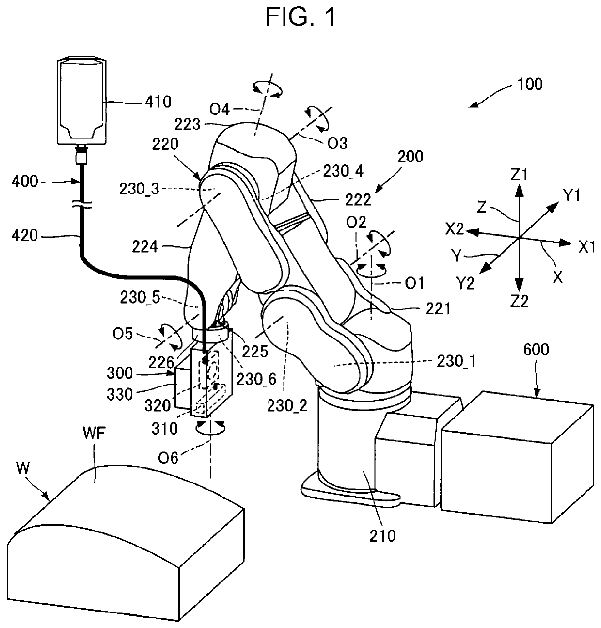
[0019]FIG. 1 is a schematic, perspective view of a three-dimensional (3D) object print apparatus 100 according to an embodiment of the present disclosure. The 3D object print apparatus 100 is configured to print information on the surface of a workpiece W having a 3D shape in accordance with ink jet scheme.

[0020]The workpiece W has a surface WF to which information is to be printed. In the example of FIG. 1, the surface WF is a bulging surface with a discontinuous curvature; however, the information may be printed on another surface of the workpiece W. In addition, the dimensions, shape, and orientation of the workpiece W disposed are not limited to those in FIG. 1, and it may have any other dimensions, shape, and orientation.

[0021]In the example of FIG. 1, the 3D object print apparatus 100 is an ink jet printer that includes a vertical articulated robot. As illustrated in FIG. 1, the 3D object print apparatus 100 ...

first modification

[0113]A moving mechanism is a six-axis vertical articulated robot in the foregoing embodiment; however, the moving mechanism is not limited to this configuration. The moving mechanism has only to change a location and posture of a liquid ejecting head relative to a workpiece in a 3D manner. Thus, the moving mechanism may be a vertical articulated robot having a plurality of axes other than six or a multi-axis horizontal articulated robot. A movable part of the robot arm is not limited to a rotation mechanism; alternatively, the movable part may be an expansion mechanism.

second modification

[0114]A liquid ejecting head is fixed to a second end of the robot arm with screws in the foregoing embodiment; however, the fixing mechanism is not limited to this configuration. Alternatively, the liquid ejecting head may be fixed to the second end of the robot arm with a holding mechanism such as a robot hand. In which case, this holding mechanism may be provided at the second end of the robot in order to hold the ejection head.


PUM

PropertyMeasurementUnit
anglesaaaaaaaaaa
angleaaaaaaaaaa
angleaaaaaaaaaa

Abstract

A three-dimensional object print apparatus performs a first step at which a liquid ejecting head ejects liquid onto a workpiece and simultaneously a moving mechanism changes a location of the liquid ejecting head relative to the workpiece along a first route and further performs a second step at which an energy emitting section irradiates the liquid on the workpiece with energy and simultaneously the moving mechanism changes the location of the liquid ejecting head relative to the workpiece along a second route. In this case, L1<L2 at the first step and L1>L2 at the second step, where L1 denotes a distance in a direction normal to a nozzle surface of the liquid ejecting head between the workpiece and the nozzle surface, and L2 denotes a distance in a direction normal to an emission surface of the energy emitting section between the workpiece and the emission surface.

Description

[0001]The present application is based on, and claims priority from JP Application Serial Number 2020-175184, filed Oct. 19, 2020, the disclosure of which is hereby incorporated by reference herein in its entirety.BACKGROUND1. Technical Field[0002]The present disclosure relates to a 3D object print apparatus and method.2. Related Art[0003]Three-dimensional (3D) object print apparatuses known in the art are configured to print information on the surface of an object having a 3D shape in accordance with ink jet scheme. As an example, JP-T-2015-520011 discloses a 3D object print apparatus that includes: a robot; and a print head disposed in the robot. This print head ejects ink droplets onto a curved surface of a vehicle.[0004]The disclosed 3D print apparatus further includes a curing head in the robot adjacent to the print head. This curing head follows the movement of the print head, thereby curing the ink on the vehicle surface immediately after the ink has been placed thereon.[0005...

Claims


Application Information

Patent Timeline
Patent Type & Authority Applications(United States)
IPC IPC(8): B29C64/106B33Y10/00B33Y30/00B29C64/227
CPCB29C64/106B29C64/227B33Y30/00B33Y10/00B41J3/4073B41J11/002B41J25/00B41J11/00214B41J11/00218B25J11/00B41M5/0088B41M7/0081B41J11/00212
Inventor KUMAGAI, MASARUISHII, YUKI
Owner SEIKO EPSON CORP
Why Eureka
Try Eureka