
Moonphase display mechanism

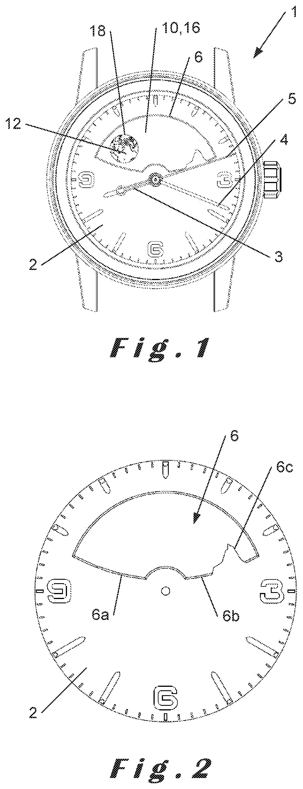
a technology of moonphase display and display mechanism, which is applied in the field of moonphase display mechanism, can solve the problems that the terminators of the various moonphases displayed cannot be made to look realistic, and none of these variants makes it possible to achieve a moonphase display

Pending Publication Date: 2022-06-02
DE LA MFG DHORLOGERIE AUDEMARS PIGUET & CIE
View PDF0 Cites 2 Cited by
  • Summary
  • Abstract
  • Description
  • Claims
  • Application Information

AI Technical Summary

Benefits of technology

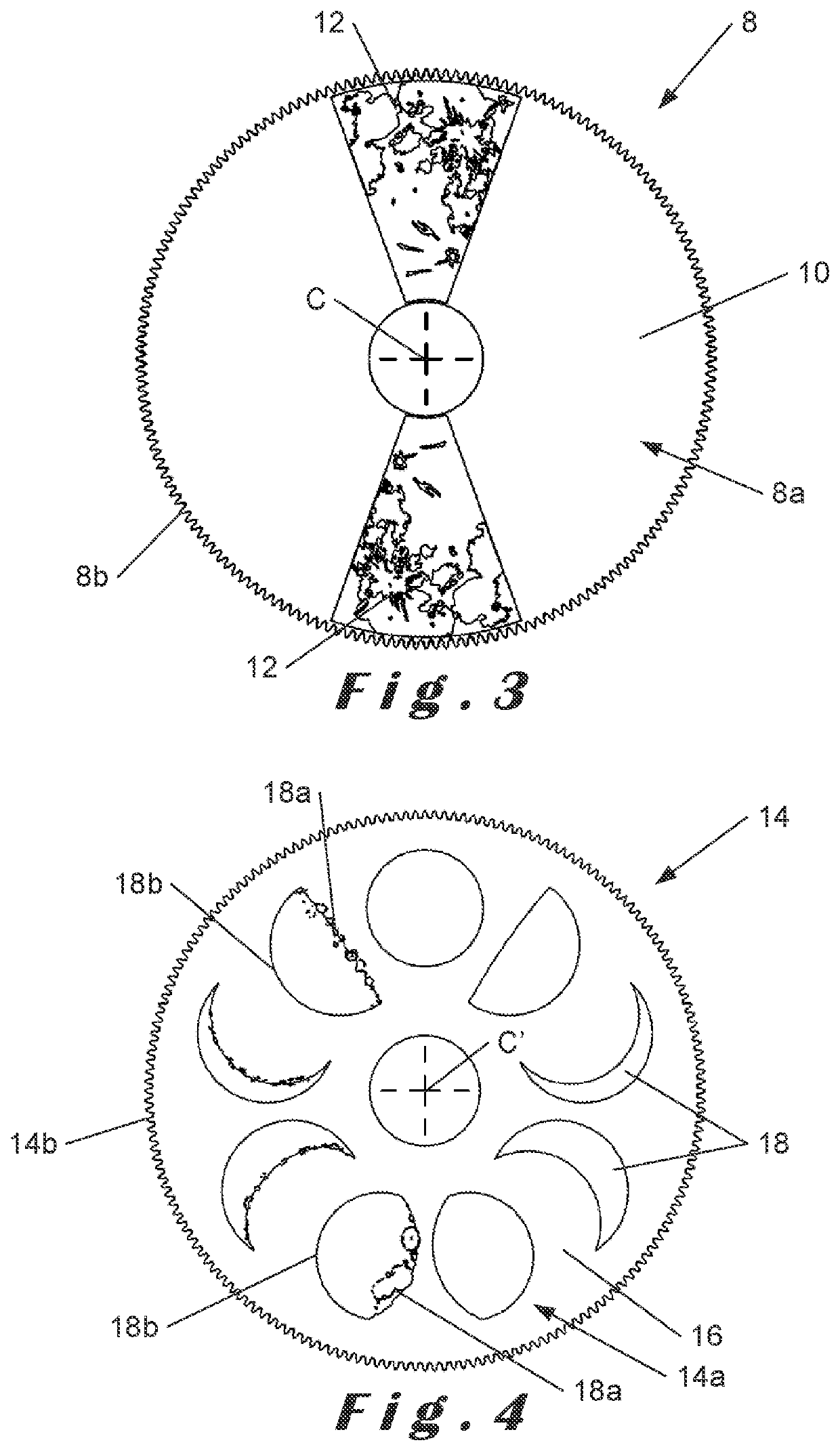
The display mechanism described in this patent allows for the realistic display of the entire moon's illuminated surface, from birth to death, by superposing a portion of the lunar background onto a profile of the second wheel and pinion. This mechanism makes it possible to select the appropriate moonphase profiles for accurate and reliable display of the moon's phases.

Problems solved by technology

However, none of these variants makes it possible to achieve a moonphase display which displays at once all the waxing and waning phases of the portion of the moon's illuminated surface visible from the earth against a sky background of large dimensions, behind a horizon independent of the displayed moon profile.
Furthermore, the configuration of the apertures means that the terminators of the various moonphases displayed cannot be made to look realistic.

Method used


Image

  • Moonphase display mechanism
  • Moonphase display mechanism
  • Moonphase display mechanism

Examples


first embodiment

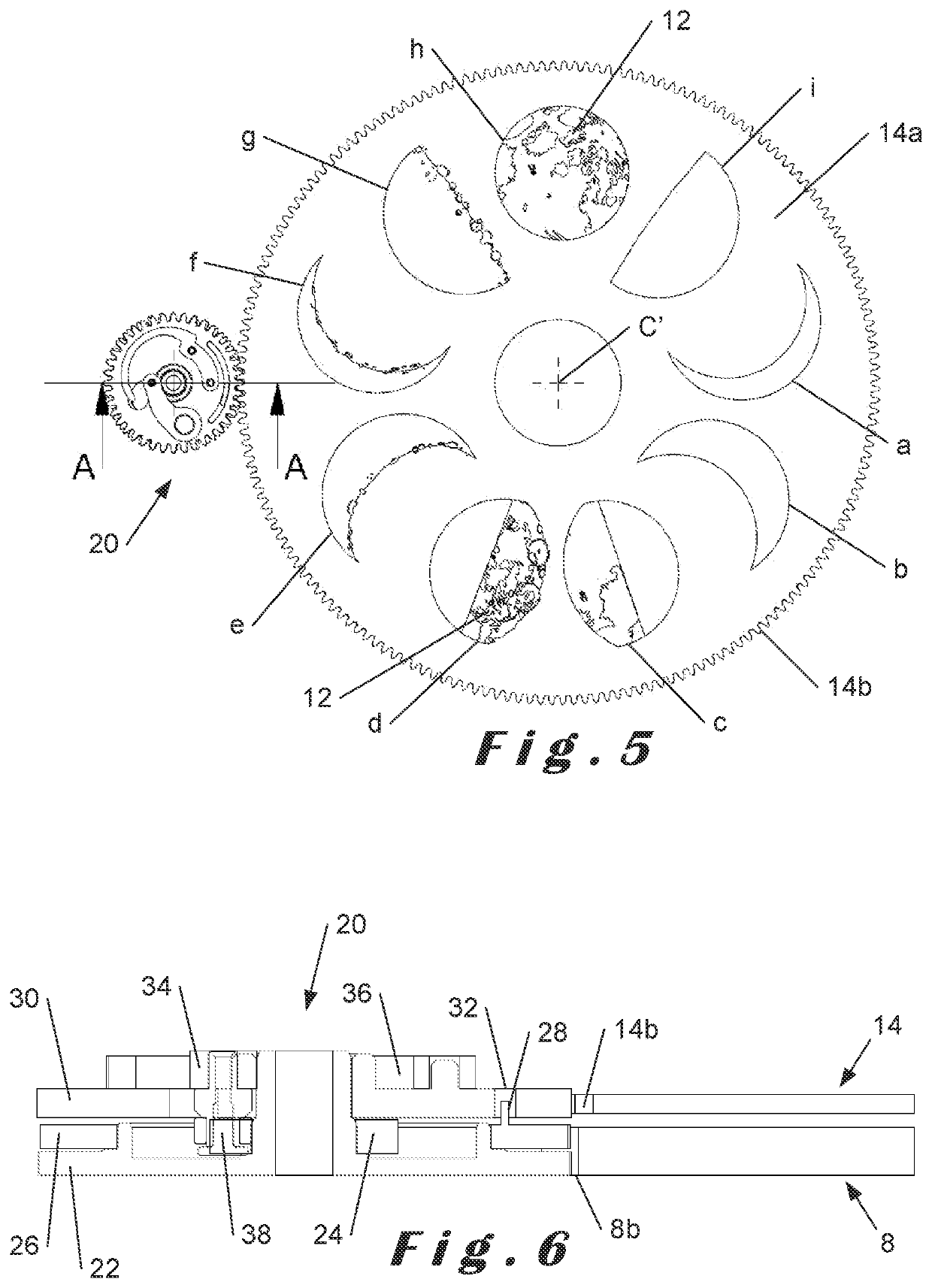
[0055] the drive device comprises an energy accumulator arranged to be driven by the first wheel and pinion 8 which is itself driven by the drive gear train, and arranged to cause the second wheel and pinion 14 to jump forward under the action of said energy accumulator during the transitional period.

[0056]Such a drive device is for example shown in FIGS. 5 to 8.

[0057]In this first embodiment, the drive device with energy accumulator 20 comprises three wheels coaxially superposed along an axis parallel to the central axis, namely a first toothed wheel 22 arranged to be driven by the first wheel and pinion 8 by means of its external teeth 8b. Said first wheel 22 is integral with a cam 24 which here for example comprises four sectors.

[0058]The drive device with energy accumulator 20 also comprises a second toothed wheel 26 arranged also to be driven by said first wheel and pinion 8 via its external teeth 8b, but at a higher velocity than the first wheel 22. To this end, said first and...

second embodiment

[0076]FIGS. 14 to 16 show the drive device used in the invention.

[0077]In this embodiment, the drive device comprises a drive wheel and pinion 40 mounted on the first wheel and pinion 8′ which is driven by the drive gear train, said drive wheel and pinion 40 comprising a drive wheel 42 arranged to cooperate with the second wheel and pinion 14′, and a Maltese cross 44, said drive wheel and pinion 40 being arranged to be rotationally immobile in relation to said first wheel and pinion 8′ for synchronised drive of the first and second wheels and pinions 8′, 14′ via the drive wheel 42 during the display period, and to be driven in rotation in relation to said first wheel and pinion 8′ in order instantaneously to cause the drive wheel 42 to pivot in order to drive the second wheel and pinion 14′ in rotation by the repositioning angle during the transitional period.

[0078]More specifically with reference to FIGS. 14 and 15, the first wheel and pinion 8′ comprises a night-time background 10...


PUM


Abstract

A display mechanism for n moonphases for a timepiece, where n≥3, includes a first wheel and pinion having a night-time background and a portion of lunar background and a second wheel and pinion superposed on the first, the second having a night-time background and moonphase profiles, with the first and second pivoting about one axis. The first wheel and pinion is driven at a constant velocity, and that the second can be driven in rotation at the same velocity and direction as the first during a moonphase display period during which a portion of lunar background of the first and a moonphase profile of the second corresponding to the moonphase to be displayed are superposed, revealing the moonphase. The second wheel and pinion is offset from the first by a repositioning angle during a transitional period between the current and following display periods, revealing the following moonphase.

Description

CROSS-REFERENCE TO RELATED APPLICATIONS[0001]This application claims priority to Swiss Patent Application No. 01526 / 20 filed Nov. 30, 2021, the entire contents of which are hereby incorporated by reference.BACKGROUND OF THE INVENTIONField of the Invention[0002]The present invention relates to a moonphase display mechanism for a timepiece, comprising a first wheel and pinion having a night-time background and at least one portion of lunar background and a second wheel and pinion superposed on the first wheel and pinion, said second wheel and pinion having a night-time background and moonphase profiles.[0003]The present invention also relates to a timepiece comprising such a display mechanism.Description of the Related Art[0004]Such a moonphase display mechanism is for example described in the applicant's published patent application EP 2 392 976. In said document, the moonphase display mechanism comprises a first moon disc comprising two light-coloured circles symbolising the moon in...

Claims


Application Information

Patent Timeline
IPC IPC(8): G04B19/26
CPCG04B19/268
Inventor REY-MERMET, GILLES
Owner DE LA MFG DHORLOGERIE AUDEMARS PIGUET & CIE
Learn More