Innovative and flexible fixture for poling plan

a flexible fixture and fixture technology, applied in the field of poling, can solve the problems of prior systems and/or devices for performing corona poling however, which have been somewhat limited in one way or another, prior systems did not provide a robust monitoring mechanism for poling process, and other systems and/or devices where limited to performing corona

Pending Publication Date: 2022-06-02
XEROX CORP
View PDF0 Cites 0 Cited by
  • Summary
  • Abstract
  • Description
  • Claims
  • Application Information

AI Technical Summary

Problems solved by technology

Prior systems and / or devices for performing corona poling however have been somewhat limited in one way or another.
For example, some prior systems did not provide a robust mechanism for monitoring the poling process.
Other systems and / or devices where limited to performing corona poling at a nominal room temperature.
Additionally, poling using a corona generated at a tip of a wire limits the area of a sample which can be poled at a given time, thereby potentially increasing the time in which it takes to pole an entire sample.

Method used


Image

  • Innovative and flexible fixture for poling plan
  • Innovative and flexible fixture for poling plan
  • Innovative and flexible fixture for poling plan

Examples


Embodiment Construction

[0013]For clarity and simplicity, the present specification shall refer to structural and / or functional elements, relevant standards, algorithms and / or protocols, and other components, methods and / or processes that are commonly known in the art without further detailed explanation as to their configuration or operation except to the extent they have been modified or altered in accordance with and / or to accommodate the preferred and / or other embodiment(s) presented herein. Moreover, the apparatuses and methods disclosed in the present specification are described in detail by way of examples and with reference to the figures. Unless otherwise specified, like numbers in the figures indicate references to the same, similar or corresponding elements throughout the figures. It will be appreciated that modifications to disclosed and described examples, arrangements, configurations, components, elements, apparatuses, methods, materials, etc. can be made and may be desired for a specific app...


PUM


Abstract

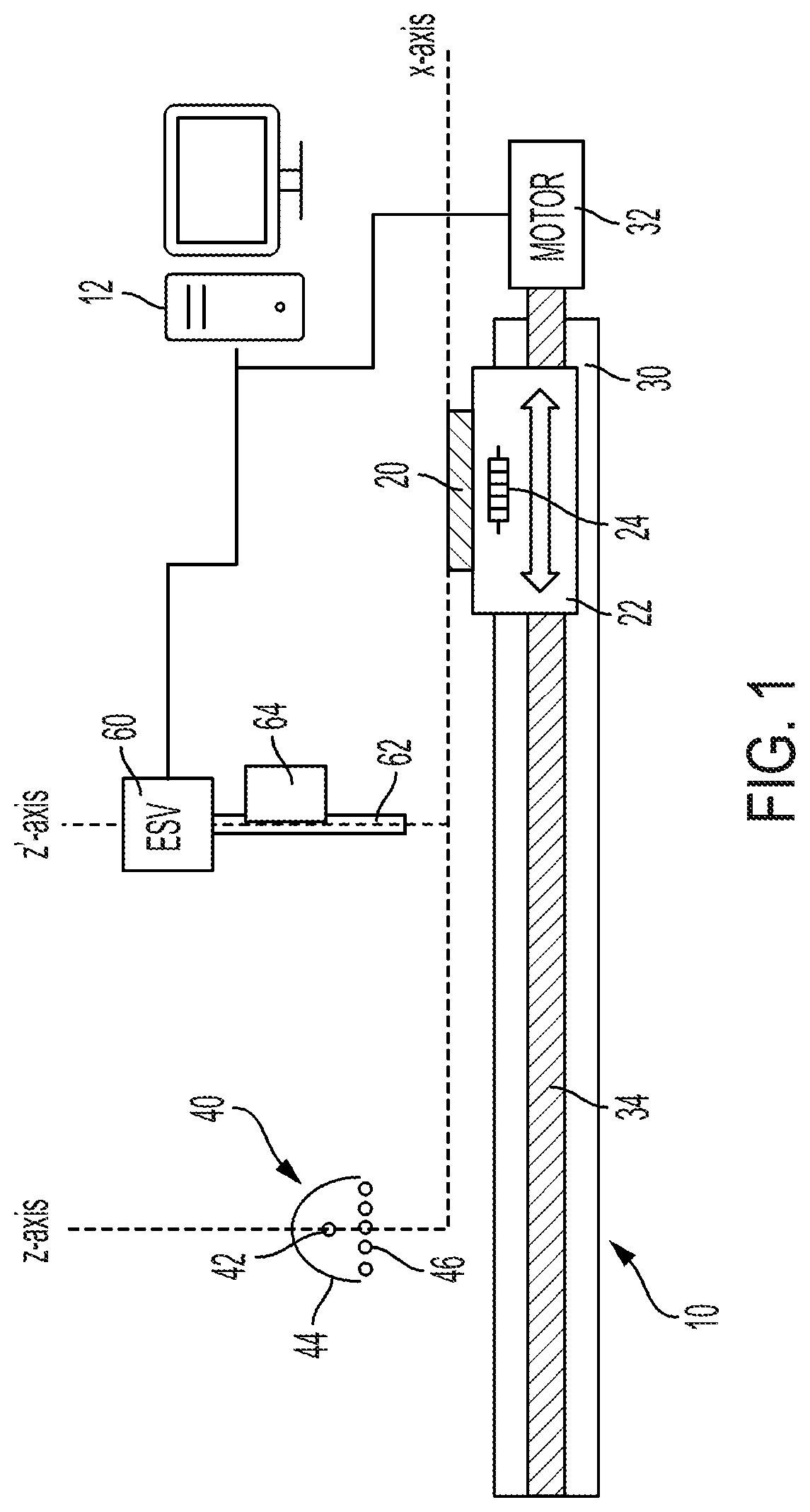
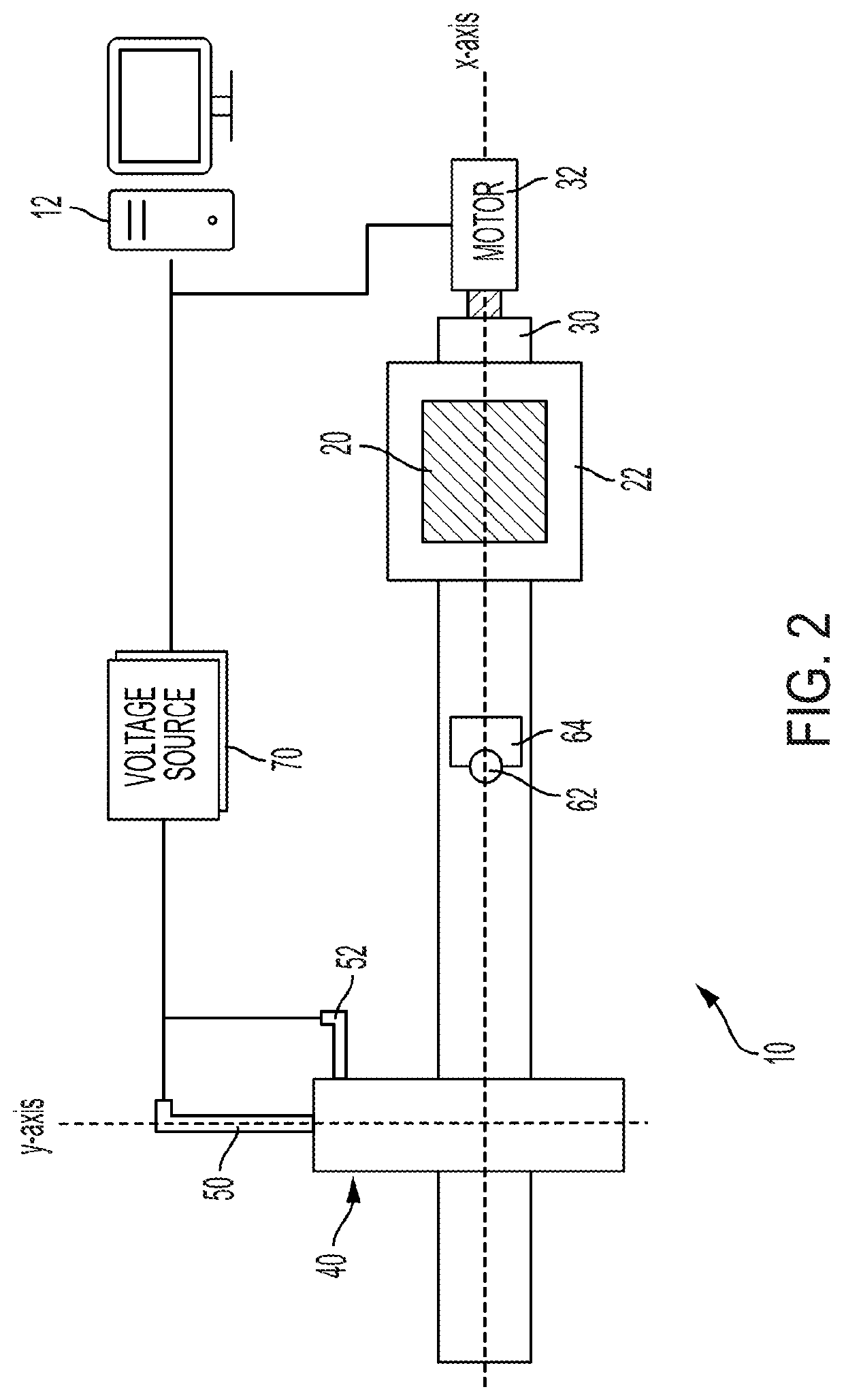
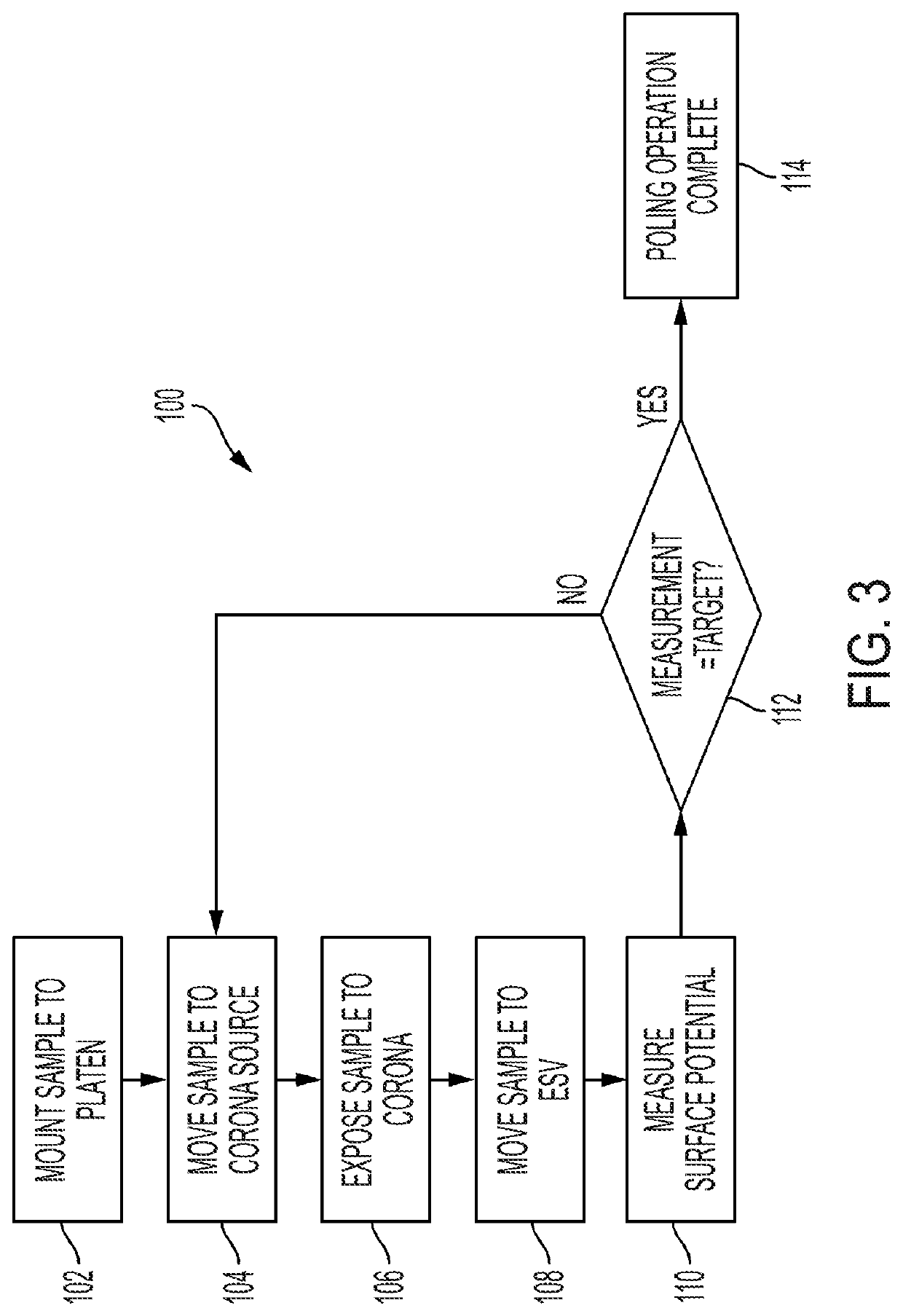
An apparatus 10 for poling piezoelectric material includes a platen 22 which holds a sample 20 of piezoelectric material to be poled and a stage 30 to which the platen is mounted. The stage 30 is arranged to selectively move the platen 22 and thereby the sample 20 which the platen 22 holds. The platen 22 is movable by the stage 30 selectively between a first position and a second position. A corona source 40 generates a corona to which the sample 20 is exposed when the platen 22 is moved to the first position by the stage 30. An electrostatic voltmeter 60 having a probe 62 measures a surface potential of the sample 20 when the platen 22 is moved to the second position by the stage 30.

Description

BACKGROUND[0001]The present specification relates to the poling of piezoelectric materials.[0002]Generally, for a piezoelectric material to function as desired, the electric dipoles within a sample material are made to align via a process commonly known as poling. This is typically achieved in one of two ways. In a one approach, a flat sample material is placed between two parallel plate electrodes, submerged in a high dielectric medium, and subjected to very high direct current electric field (e.g. 3 kV / mm). In another approach, the sample material is charged using a process referred to as “corona poling.” In conventional corona poling, the sample material is typically placed between a grounded electrode and a wire tip. Corona is generated at the tip of the wire by applying high voltage to the wire. Conventional corona poling is commonly carried out at room temperature.[0003]Prior systems and / or devices for performing corona poling however have been somewhat limited in one way or a...

Claims


Application Information

Patent Timeline
Patent Type & Authority Applications(United States)
IPC IPC(8): H01L41/253H01L41/33
CPCH01L41/253H01T19/00H01L41/33H10N30/045H10N30/04H10N30/08
Inventor JUNGINGER, JOHANNBURKE, SIMONVELLA, SARAH
Owner XEROX CORP
Why Eureka
Try Eureka