Method for adjusting multicast broadcast service area and network apparatus using the same

Pending Publication Date: 2022-06-30
IND TECH RES INST
9 Cites 0 Cited by

AI-Extracted Technical Summary

Problems solved by technology

If there is a gap between the broadcast area actually required and the MBSFN area preset by the telecom operator, generally, some base stations may allocate radio spectrum resources to perform unnecessary broadcast services, and some user equipments may thus receive broadcast information irrelevant to themselves, thus wasting the radio spectru...

Abstract

An aspect of the disclosure includes a method for adjusting a multicast broadcast service area. According to an exemplary embodiment, the method may include, but is not limited to, the following steps. A cell list in a session update request message is obtained. An old broadcast target area for a multicast broadcast service is adjusted to a new broadcast target area for the multicast broadcast service according to the cell list. At least one base station is controlled to allocate or release radio spectrum resources for the multicast broadcast service.

Application Domain

Special service provision for substationAssess restriction +3

Technology Topic

EngineeringBroadcast service +4

Image

  • Method for adjusting multicast broadcast service area and network apparatus using the same
  • Method for adjusting multicast broadcast service area and network apparatus using the same
  • Method for adjusting multicast broadcast service area and network apparatus using the same

Examples

  • Experimental program(1)

Example

[0024]To make the aforementioned and other features of the disclosure more comprehensible, exemplary embodiments accompanied with figures will be described in detail below. It is to be understood that both the foregoing general description and the following detailed description are exemplary, and are intended to provide further description of the disclosure as claimed.
[0025]In the disclosure, the terminology of the LTE standard specified by the Third Generation Partnership Project (3GPP) will be adopted for description of the exemplary embodiments. However, the same concept presented in the disclosure may be applied by those of ordinary skill in the art to any other communication system, e.g., a communication system using the 5G standard or other standards.
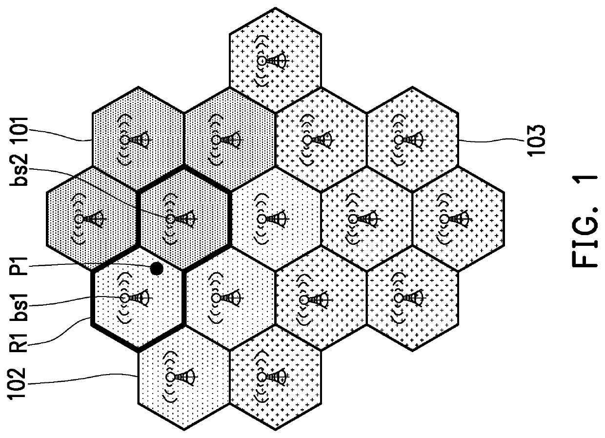
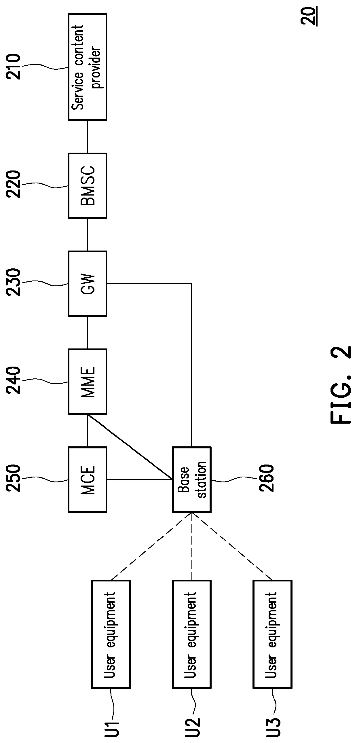
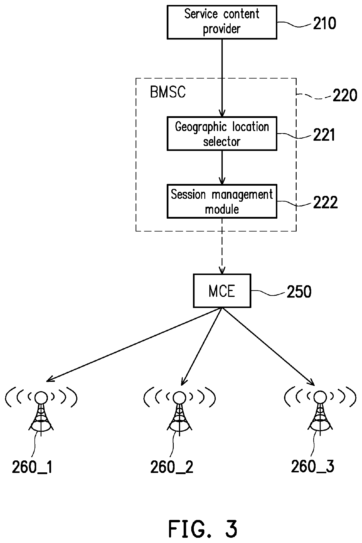
[0026]The network apparatus disclosed in the disclosure may be, for example, a multi-cell/multicast coordination entity (MCE) in a radio access network but is not limited thereto. The network apparatus is configured to manage spectrum resources for a multicast broadcast service, so that multiple base stations may use the same spectrum resources to simultaneously perform broadcast. The network apparatus of this embodiment of the disclosure may be connected to a multicast broadcast service control apparatus, and the multicast broadcast service control apparatus may be, for example, a broadcast multicast service center (BMSC). In an embodiment, the network apparatus may receive related messages of a multicast broadcast service, such as a session start request message, a session update request message, or other related messages, from the multicast broadcast service control apparatus.
[0027]In an embodiment, the multicast broadcast service control apparatus may obtain event-related information of an event from a service content provider. For example, the multicast broadcast service control apparatus may obtain a V2X message of a V2X service from the service content provider, and the V2X message may include event-related information of a road event. The event-related information may include an event coordinate location and a broadcast range. The multicast broadcast service control apparatus may determine a broadcast target area associated with the event according to the event coordinate location, the broadcast range, and the geographic locations of multiple base stations. In an embodiment, the multicast broadcast service control apparatus may determine the broadcast target area of the V2X message according to the event coordinate location, the broadcast range, and the geographic locations of multiple base stations to broadcast the V2X message by using the multicast broadcast service via multiple base stations. In an embodiment, when a V2X service uses the multicast broadcast service, the broadcast target area in the disclosure may be dynamically adjusted according to the location of the road event.
[0028]In an embodiment, after the multicast broadcast service control apparatus determines a new broadcast target area, the multicast broadcast service control apparatus may send a session update request message to the network apparatus, and the session update request message includes a cell list corresponding to the new broadcast target area. Therefore, the network apparatus may adjust an old broadcast target area for the multicast broadcast service to the new broadcast target area for the multicast broadcast service according to the cell list in the session update request message. Then, the network apparatus may control at least one base station to allocate or release radio spectrum resources for the multicast broadcast service. It is noted that the coverage of the broadcast target area (i.e., the old broadcast target area and the new broadcast target area) may be different from the range of one MBSFN area or the range composed of multiple MBSFN areas.
[0029]To describe the disclosure in more details, an example in which the network apparatus is an MCE and the multicast broadcast service control apparatus is a BMSC will be described below.
[0030]FIG. 2 is a schematic view showing an MBMS architecture according to an embodiment of the disclosure. Referring to FIG. 2, in an embodiment, an MBMS architecture 20 may include a service content provider 210, an BMSC 220, a gateway (GW) 230, a mobility management entity (MME) 240, an MCE 250, a base station 260, and multiple user equipments U1 to U3. In an embodiment, reference may be made to the current standards of the 3GPP communication protocols TS 23.246 and TS 36.300 for descriptions of the operations and functions of each device and network entity in the MBMS architecture 20 shown in FIG. 2.
[0031]The service content provider 210 may provide event-related information and a broadcast service content to the BMSC 220. For example, the service content provider 210 may provide a V2X message to the BMSC 220. The BMSC 220 is generally located in the core network and is responsible for session registration and authorization of the service content provider 210. When a new multicast broadcast session starts, the BMSC 220 receives session registration of the service content provider 210, and then the BMSC 220 sends a session start request message to the corresponding MME 240 via the GW 230. The MME 240 forwards the session start request message to the MCE 250, and the MCE 250 may allocate radio spectrum resources to the newly added multicast broadcast session. The MCE 250 may send a scheduling information message to the base station 260 according to the resource allocation result to have the base station 260 perform broadcast according to the radio spectrum resources indicated by the MCE 250. Accordingly, user equipments U1 to U3 located within the coverage of the base station 260 can all receive the broadcast service content from the base station 260.
[0032]In an embodiment, the BMSC 220 has geographic locations of multiple base stations (including the base station 260). The BMSC 220 may obtain event-related information from the service content provider 210, and screen and obtain part of the base stations related to the event according to the geographic locations of the multiple base stations and the event-related information to thereby determine the broadcast target area. The BMSC 220 may determine whether the broadcast target area has changed. In response to a change in the broadcast target area (i.e., a change in the set of cells making up the broadcast target area), the BMSC 220 may send a session update request message including a cell list to the MCE 250 to notify the MCE 250 to update the broadcast target area. The cell list may include cell IDs of multiple cells.
[0033]FIG. 3 is a schematic view showing cooperative adjustment of the broadcast target area by the BMSC and the MCE according to an embodiment of the disclosure. Referring to FIG. 3, the BMSC 220 may include a geographic location selector 221 and a session management module 222. The service content provider 210 may provide event-related information to the geographic location selector 221. The geographic location selector 221 may determine the target broadcast area of the multicast broadcast session according to the event-related information and geographic locations of multiple base stations. The session management module 222 may determine whether the broadcast target area has changed. In response to a change in the broadcast target area (i.e., the old broadcast target area determined at a previous time is different from the new broadcast target area determined at the current time), the session management module 222 may send a session update request message including a cell list to the MCE 250 to notify the MCE 250 to update the broadcast target area.
[0034]When the MCE 250 receives the session update request message, the MCE 250 may obtain the cell list in the session update request message and thereby obtain the new broadcast target area. Therefore, the MCE 250 may adjust the old broadcast target area for the multicast broadcast service to the new broadcast target area for the multicast broadcast service according to the cell list. More specifically, by comparing the cells in the cell list with the cells in the old broadcast target area, the MCE 250 may add cells to the old broadcast target area or remove cells from the old broadcast target area to update the broadcast target area. In addition, the MCE 250 may notify base stations 260_1 to 260_3 whether to perform broadcast, and send a scheduling information message to the base stations 260_1 to 260_3 to control the base stations 260_1 to 260_3 to allocate or release the radio spectrum resources for the multicast broadcast service.
[0035]It is noted that, although the determination of the broadcast target area in the disclosure is not associated with the MBSFN area, the embodiments of the disclosure may be compatible with the current standard in the 3GPP communication protocol for performing the multicast broadcast service according to the MBSFN area. In an embodiment, the MCE 250 may identify that the multicast broadcast service session is in a first mode or a second mode, e.g., a geographic location mode and an MBSFN mode, respectively. Correspondingly, the MCE 250 may allocate a first resource pool used for the first mode and a second resource pool used for the second mode. The allocation status of the first resource pool and the second resource pool may be recorded in the MCE 250. Specifically, based on each registered multicast broadcast service session, the MCE 250 may respectively allocate corresponding available resources according to whether the multicast broadcast service session is in the first mode or the second mode, thereby dividing the available resources into the first resource pool used for the first mode and the second resource pool used for the second mode.
[0036]FIG. 4A is a schematic view showing the first resource pool and the second resource pool allocated by the MCE according to an embodiment of the disclosure. Referring to FIG. 4A, the MCE 250 may allocate subframes (SF) numbered ‘1’, ‘2’, ‘3’, ‘6’, ‘7’, and ‘8’ as multicast broadcast service subframes. The multicast broadcast service subframes are, for example, MBSFN subframes. The MCE 250 may divide the multicast broadcast service subframes into a first resource pool Po1 used for the geographic location mode and a second resource pool Po2 used for the MBSFN mode. The resource elements (RE) in the first resource pool Po1 are allocated to the multicast broadcast service belonging to the geographic location mode, and the resource elements in the second resource pool Po2 are allocated to the multicast broadcast service belonging to the MBSFN mode. In other words, the resource elements in the first resource pool Po1 may be configured to transmit a broadcast service content of one multicast broadcast service belonging to the geographic location mode. The resource elements in the second resource pool Po2 may be configured to transmit a broadcast service content of another multicast broadcast service belonging to the MBSFN mode.
[0037]FIG. 4B is a schematic view showing allocation of the radio spectrum resources by the base station for the multicast broadcast service according to the embodiment shown in FIG. 4A. Referring to FIG. 4B, when no event occurs, the multicast broadcast service session is in a suspended state, and in the case where the MCE 250 has recorded that the resource elements in the first resource pool Po1 are allocated to the multicast broadcast service in the geographic location mode, the MCE 250 does not notify the base station to allocate the resource elements in the first resource pool Po1 to perform broadcast, so the base station may use the resource elements in the first resource pool Po1 to perform unicast. When an event occurs (i.e., when the BMSC receives a broadcast service content from the service content provider), the multicast broadcast service session is set to an active state. As the MCE 250 has allocated and reserved resource elements 41, 42, 43, 44, and 45 in the first resource pool Po1 to the multicast broadcast service belonging to the geographic location mode, the MCE 250 may further notify the base station to allocate the resource elements 41, 42, 43, 44, and 45 in the first resource pool Po1 to perform broadcast. It is noted that, in the case where the MCE 250 does not notify the base station to allocate other resource elements in the first resource pool Po1 to perform broadcast, the base station can still use other resource elements in the first resource pool Po1 determined by the MCE 250 to perform unicast. On the other hand, in this example, when the base station uses the resource elements 41, 42, 43, 44, and 45 to perform the multicast broadcast service in the geographic location mode, the base station may simultaneously use the resource elements in the second resource pool Po2 to perform a multicast broadcast service in the MBSFN mode.
[0038]FIG. 5 is a flowchart showing an initialization process for initiating a multicast broadcast session according to an embodiment of the disclosure. Referring to FIG. 5, in step S501, the service content provider 210 may register a multicast broadcast service session with the BMSC 220. In step S502, the BMSC 220 may configure a flag Flag_Geo_Location_Mode associated with the multicast broadcast service session according to the registration information provided by the service content provider 210 to indicate that the multicast broadcast service session belongs to the geographic location mode or the MBSFN mode. In step S503, the BMSC 220 may send a session start request message of the multicast broadcast service to the gateway 230, the MME 240, the MCE 250, and the base station 260. In step S504, the MCE 250 may obtain the flag Flag_Geo_Location_Mode in the session start request message of the multicast broadcast service to determine that the multicast broadcast service belongs to one of the geographic location mode and the MBSFN mode according to the flag Flag_Geo_Location_Mode. In step S505, in response to the flag Flag_Geo_Location_Mode matching a predetermined value (e.g., the flag Flag_Geo_Location_Mode is equal to 1), the MCE 250 determines that the multicast broadcast service belongs to the geographic location mode and suspends the multicast broadcast service. In other words, when the multicast broadcast service belongs to the geographic location mode, the MCE 250 first configures the multicast broadcast service session as the suspended state. In step S506, the MCE 250 may notify the base station 260 to configure the multicast broadcast service session as the suspended state through a scheduling information message. Although the MCE 250 has allocated the first resource pool to the multicast broadcast service in the geographic location mode, it does not notify the base station of the allocation result, and when the multicast broadcast service session is in the suspended state, the base station may still use the resource elements in the first resource pool to perform unicast. In step S507, the base station 260 may send a session start response message to the BMSC 220 and the service content provider 210 via the MCE 250, the MME 240, and the gateway 230.
[0039]FIG. 6 is a flowchart showing adjustment of a broadcast target area according to an embodiment of the disclosure. The steps shown in FIG. 6 may be executed by the BSMC 220. Referring to FIG. 6, in step S601, the BSMC 220 receives event-related information from the service content provider 210. In step S602, the BSMC 220 screens and obtains multiple target base stations to determine a new broadcast target area. In step S603, the BSMC 220 determines whether the new broadcast target area is identical to an old broadcast target area. If the determination in step S603 is “NO”, in step S604, the BSMC 220 sends a session update request message including a cell list to the MCE 250, so that the MCE 250 can update the broadcast target area according to the cell list. The cell list indicates multiple target base stations of the new broadcast target area. After the MCE 250 completes the allocation of the radio spectrum resources, in step S605, the BSMC 220 receives a session update reply message from the MCE 250. In step S606, in response to receiving the session update reply message, the BSMC 220 starts to send a broadcast service content of the multicast broadcast service. If the determination in step S603 is “YES”, the BSMC 220 may directly execute step S606.
[0040]FIG. 7 is a flowchart showing adjustment of a broadcast target area according to an embodiment of the disclosure. The steps shown in FIG. 7 may be executed by the MCE 250. Referring to FIG. 7, in step S701, the MCE 250 receives a session update request message from the BSMC 220. In step S702, the MCE 250 obtains a cell list in the session update request message. In step S703, the MCE 250 determines whether the cell list includes a first cell to be added. If the determination in step S703 is “YES”, in response to the cell list including the first cell but the old broadcast target area not including the first cell, the MCE 250 adjusts the old broadcast target area to a new broadcast target area by adding the first cell, and controls the base station of the first cell to allocate the radio spectrum resources. Therefore, in step S704, the MCE 250 notifies a first base station corresponding to the first cell to configure the state of the multicast broadcast session as the active state, and controls the first base station corresponding to the first cell to allocate the radio spectrum resources for the multicast broadcast service.
[0041]In step S705, the MCE 250 determines whether the old broadcast target area includes a second cell to be removed. If the determination in step S705 is “YES”, in response to the old broadcast target area including the second cell but the cell list not including the second cell, the MCE 250 adjusts the old broadcast target area to the new broadcast target area by removing the second cell. Therefore, in step S706, the MCE 250 notifies a second base station corresponding to the second cell to configure the state of the multicast broadcast session as the suspended state, and sends a scheduling information message to control the second base station corresponding to the second cell to release the radio spectrum resources for the multicast broadcast service. In step S707, the MCE 250 returns a session update reply message to the BSMC 220. In an embodiment, after the MCE 250 updates the broadcast target area and completes the allocation of the radio spectrum resources, multiple target base stations of the new broadcast target area may start the multicast broadcast service. Based on the resource elements in the first resource pool reserved by the MCE 250 for the multicast broadcast service belonging to the geographic location mode, the target base station may allocate the resource elements in the first resource pool based on the notification of the MCE to send a broadcast service content, and the target base station sends the broadcast service content according to the same resource elements.
[0042]FIG. 8A and FIG. 8B are schematic views showing adjustment of a broadcast target area according to an embodiment of the disclosure. Referring to FIG. 8A first, in response to occurrence of a road event, the geographic location selector 221 of the BMSC 220 may screen and obtain a cell #1 and a cell #2 according to event-related information and database knowledge and provide cell IDs of the cell #1 and the cell #2 to the session management module 222. The combination of the cell #1 and the cell #2 is the new broadcast target area. Based on the old broadcast target area being a combination of the cell #2 and a cell #3, the session management module 222 determines that the new broadcast target area is different from the old broadcast target area. Therefore, the session management module 222 updates the broadcast target area of the multicast broadcast service according to the cell #1 and the cell #2, the session management module 222 sends a session update request message including a cell list to the MCE 250, and the cell list includes the cell IDs of the cell #1 and the cell #2.
[0043]Referring to FIG. 8B next, after receiving a session update request message Msg1, the MCE 250 checks a cell list 84 in the session update request message Msg1. In response to the cell list 84 including the cell #1 but the old broadcast target area 85 not including the cell #1, the MCE 250 adds the cell #1. In response to the cell list 84 not including the cell #3 but the old broadcast target area 85 including the cell #3, the MCE 250 removes the cell #3. Therefore, the MCE 250 can adjust the old broadcast target area 85 to the new broadcast target area 86.
[0044]In response to adjusting the old broadcast target area 85 to the new broadcast target area 86, the MCE 250 may send a scheduling information message to a base station 860 of the cell #1 to control the base station 860 to configure the multicast broadcast service session as the active state and allocate the radio spectrum resources RS1. In this example, the base stations 860 and 870 may use five resource elements (five subframes (SF num=5)) to send the broadcast service content according to the resource allocation result of the MCE 250, but this is only an example and is not intended to limit the disclosure. In addition, in response to adjusting the old broadcast target area 85 to the new broadcast target area 86, the MCE 250 may send a scheduling information message to a base station 880 of the cell #3 to control the base station 880 to configure the multicast broadcast service session as the suspended state and release the radio spectrum resources RS1. As shown in FIG. 8B, in an embodiment, since both the old broadcast target area 85 and the new broadcast target area 86 include the cell #2, the MCE 250 may skip sending a scheduling information message to the base station 870 of the cell #2.
[0045]FIG. 9 is a schematic view showing allocation of the radio spectrum resources according to an embodiment of the disclosure. Referring to FIG. 9, the broadcast target area of a multicast broadcast service 91 belonging to the geographic location mode includes a cell #1 and a cell #2. The broadcast target area of a multicast broadcast service 92 belonging to the MBSFN mode includes the cell #1, the cell #2, and a cell #3. The MCE 250 may allocate a resource block RB1 composed of multiple resource elements in the first resource pool Po1 to the multicast broadcast service 91 belonging to the geographic location mode. The MCE 250 may allocate a resource block RB2 composed of multiple resource elements in the second resource pool Po2 to the multicast broadcast service 92 belonging to the MBSFN mode. As shown in FIG. 9, a base station 960 of the cell #1 and a base station 970 of the cell #2 may use the resource block RB1 to perform the multicast broadcast service 91 and use the resource block RB2 to perform the multicast broadcast service 92. On the other hand, a base station 980 of the cell #3 may use the resource block RB2 to perform the multicast broadcast service 92. It is noted that the base station 980 may use the resource elements in the first resource pool Po1 to perform a unicast service to improve the use efficiency of the radio spectrum resources.
[0046]FIG. 10 is a schematic view showing a network apparatus according to an embodiment of the disclosure. A network apparatus 1000 may include a processor 1100, a storage medium 1200, and a transceiver 1300. The processor 1100 is coupled to the storage medium 1200 and the transceiver 1300. In an embodiment, the processor 1100 is configured to implement at least the method used by the MCE 250.
[0047]The processor 1100 may be implemented by using a programmable design unit such as a microprocessor, a microcontroller, a DSP chip, and an FPGA. An individual electronic device or IC may also be used to implement the functions of the processor 1100. It is noted that the functions of the processor 1100 may be implemented by hardware or software.
[0048]The storage medium 1200 may be, for example, configured to record multiple modules or multiple applications executable by the processor 1100 and may be any type of fixed or movable random access memory (RAM), read-only memory (ROM), flash memory, hard disk drive (HDD), solid state drive (SSD), similar devices, or a combination thereof.
[0049]The transceiver 1300 may be configured to transmit and receive a signal. The signal may be a radio frequency (RF) signal, an optical signal, or a signal transmitted via a cable. The transceiver 1300 may also perform operations such as low noise amplification, impedance matching, frequency mixing, frequency up or down conversion, filtering, amplification, and the like. The analog-to-digital (A/D) converter is configured to convert a signal from an analog signal format to a digital signal format, and the digital-to-analog (D/A) converter is configured to convert a signal from a digital signal format to an analog signal format.
[0050]FIG. 11 is a flowchart showing adjustment of a multicast broadcast service area according to an embodiment of the disclosure. The steps in FIG. 11 may be executed by the network apparatus 1000 shown in FIG. 10. In step S1101, a cell list in a session update request message is obtained. In step S1102, an old broadcast target area for a multicast broadcast service is adjusted to a new broadcast target area for the multicast broadcast service according to the cell list. In step S1103, at least one base station is controlled to allocate or release radio spectrum resources for the multicast broadcast service.
[0051]In view of the above description, the disclosure provides a method for adjusting a multicast broadcast service area. According to the embodiments of the disclosure, the broadcast target area of the multicast broadcast service may be dynamically determined according to the event-related information, and the configuration of the broadcast target area is flexible and more in line with the actual requirements. Therefore, it is possible to prevent user equipments irrelevant to an event from receiving a multicast broadcast service message, which can improve the spectrum efficiency and improve the use efficiency of unicast.
[0052]No element, act, or instruction used in the detailed description of disclosed embodiments of the present application should be construed as absolutely critical or essential to the disclosure unless explicitly described as such. Also, as used herein, each of the indefinite articles “a” and “an” could include more than one item. If only one item is intended, the terms “a single” or similar expressions would be used. Furthermore, the terms “any of” followed by a listing of multiple items and/or multiple categories of items, as used herein, are intended to include “any of”, “any combination of”, “any plurality of”, and/or “any combination of pluralities of” the items and/or the categories of items, individually or in conjunction with other items and/or other categories of items. Further, as used herein, the term “set” is intended to include any number of items, including zero. Further, as used herein, the term “number” is intended to include any number, including zero.
[0053]It will be apparent to those skilled in the art that various modifications and variations can be made to the structure of the disclosed embodiments without departing from the scope or spirit of the disclosure. In view of the foregoing, it is intended that the disclosure cover modifications and variations of the disclosure provided they fall within the scope of the following claims and their equivalents.

PUM

no PUM

Description & Claims & Application Information

We can also present the details of the Description, Claims and Application information to help users get a comprehensive understanding of the technical details of the patent, such as background art, summary of invention, brief description of drawings, description of embodiments, and other original content. On the other hand, users can also determine the specific scope of protection of the technology through the list of claims; as well as understand the changes in the life cycle of the technology with the presentation of the patent timeline. Login to view more.
Why Eureka
Try Eureka