
Threaded flange for a flexible tank

Pending Publication Date: 2022-07-14
AVON ENGINEERED FABRICATIONS LLC
View PDF4 Cites 0 Cited by
  • Summary
  • Abstract
  • Description
  • Claims
  • Application Information

AI Technical Summary

Benefits of technology

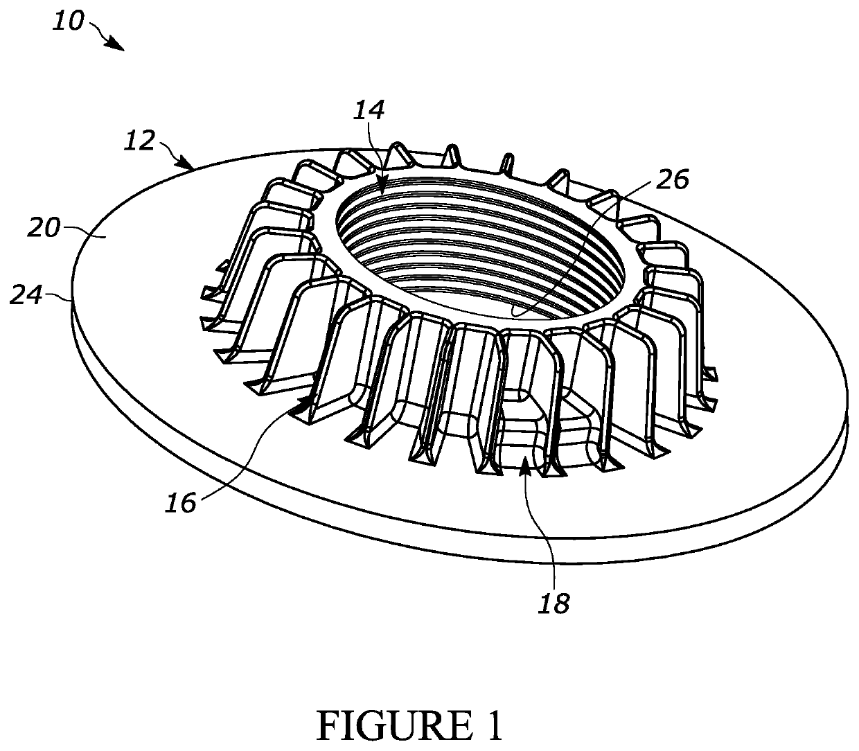
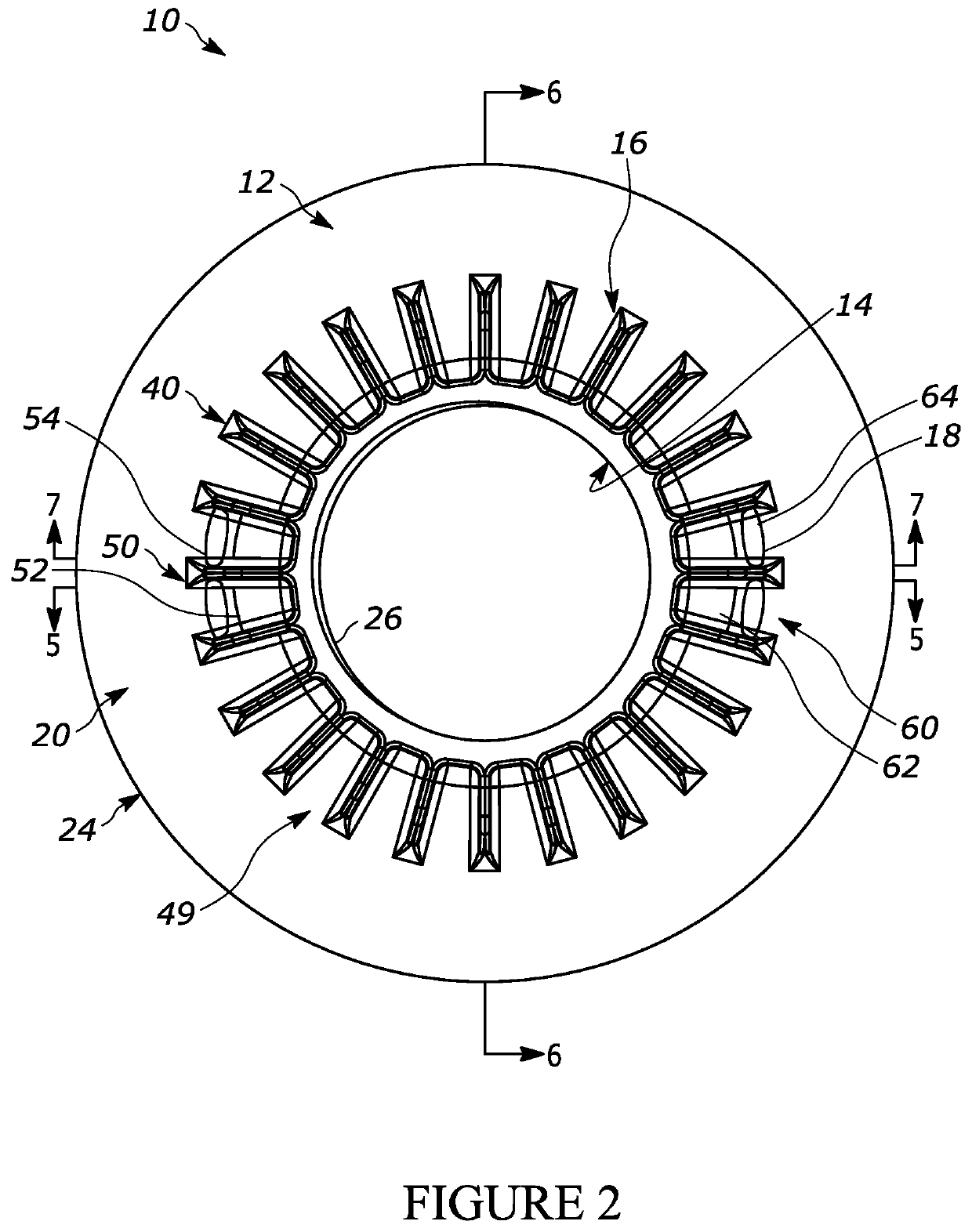
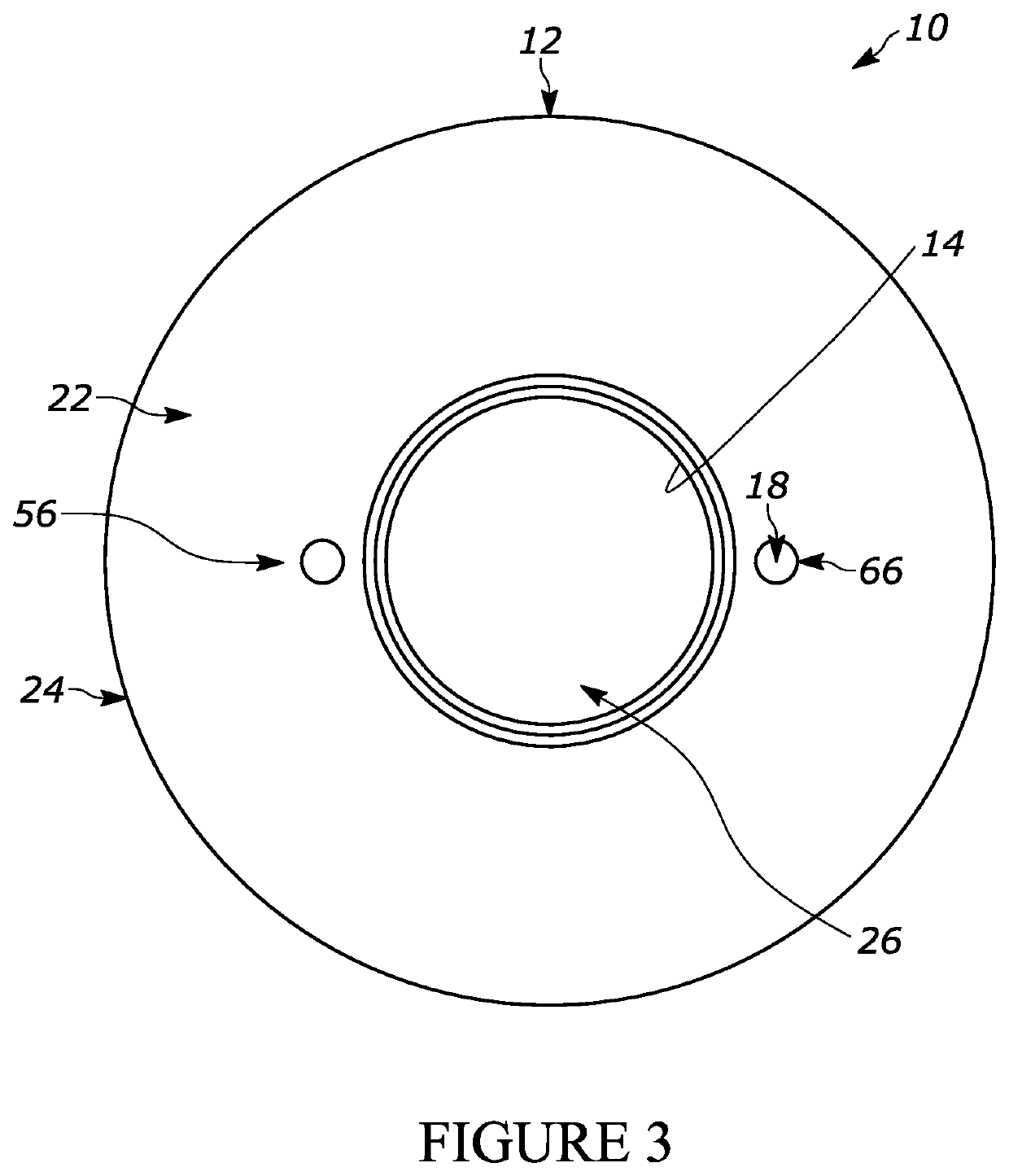
The patent is about a threaded flange for a flexible tank. The flange has a base with an upper surface and a lower surface. It has an inner opening and an outer opening. The flange has a plurality of ribs that extend outwardly from the outer surface of the upstanding passage. The flange also has a grasping member that is accessible from the lower surface of the base. The technical effect of this invention is to provide a secure and reliable flange for flexible tanks that allows for easy attachment and detachment with a tool.

Problems solved by technology

In either case, such flanges are expensive to make and / or have a propensity to leak or fail.

Method used


Image

  • Threaded flange for a flexible tank
  • Threaded flange for a flexible tank
  • Threaded flange for a flexible tank

Examples


Embodiment Construction

[0040]While this disclosure is susceptible of embodiment in many different forms, there is shown in the drawings and described herein in detail a specific embodiment(s) with the understanding that the present disclosure is to be considered as an exemplification and is not intended to be limited to the embodiment(s) illustrated.

[0041]It will be understood that like or analogous elements and / or components, referred to herein, may be identified throughout the drawings by like reference characters. In addition, it will be understood that the drawings are merely schematic representations of the invention, and some of the components may have been distorted from actual scale for purposes of pictorial clarity.

[0042]Referring now to the drawings and in particular to FIG. 1, the threaded flange is shown generally at 10. The threaded flange is configured for use in association with a flexible tank, such as a flexible tank 200. One such flexible tank is disclosed in co-pending application Ser. ...


PUM

PropertyMeasurementUnit
Angleaaaaaaaaaa
Angleaaaaaaaaaa
Angleaaaaaaaaaa

Abstract

A threaded flange for a flexible tank that has a base, an upstanding passage, an upstanding support assembly and a grasping member. The base has an upper surface, and a lower surface opposite the upper surface, and an outer perimeter and an inner opening. The upstanding passage extends upwardly away from the upper surface of the base and has a lower end and an upper end, an inner surface and an outer surface, with the inner surface being threaded. The upstanding support assembly comprises a plurality of ribs extending outwardly from the outer surface of the upstanding passage and upwardly from the upper surface of the base. The grasping member is accessible from the lower surface of the base, wherein the grasping member is accessible by and structurally configured for coupling with a tool.

Description

CROSS-REFERENCE TO RELATED APPLICATION[0001]NABACKGROUND OF THE DISCLOSURE1. Field of the Disclosure[0002]The disclosure relates in general to a threaded flange, and more particularly, to a threaded flange suitable for use in association with a flexible tank, to, in turn, provide an inlet, outlet, and / or venting for the cavity formed by the flexible tank.2. Background Art[0003]Flexible tanks for the storage of different materials are known. Some such flexible tanks are flexible in nature and can be utilized to store liquids, including but not limited to water, fuel, chemicals, gels, suspensions, among others, typically flowable material termed liquids (wherein the term fluid comprises a liquid in the definition of one of the four fundamental states of matter). Such flexible tanks are often made of a woven fabric made from fibers (typically a polymer such as nylon) and coated with polymers (such as polyurethane of polyethylene, among others). These materials are exemplary and not to ...

Claims


Application Information

Patent Timeline
IPC IPC(8): F16L23/032F16L47/14F16L13/02
CPCF16L23/032F16L13/02F16L47/14B65D75/5877B65D1/00
Inventor BUTLER, JOSHUALAUGA, TRINITYHOMES, ROBERT
Owner AVON ENGINEERED FABRICATIONS LLC
Learn More