
Grinder device

a grinding device and grinder technology, applied in the field of grinding devices, can solve the problems of inability to visually confirm the secure attachment and/or detect tampering, the illustrations are merely representational, and the effect of not being able to scale up

Pending Publication Date: 2022-08-11
MCCORMICK & CO INC
View PDF2 Cites 1 Cited by
  • Summary
  • Abstract
  • Description
  • Claims
  • Application Information

AI Technical Summary

Benefits of technology

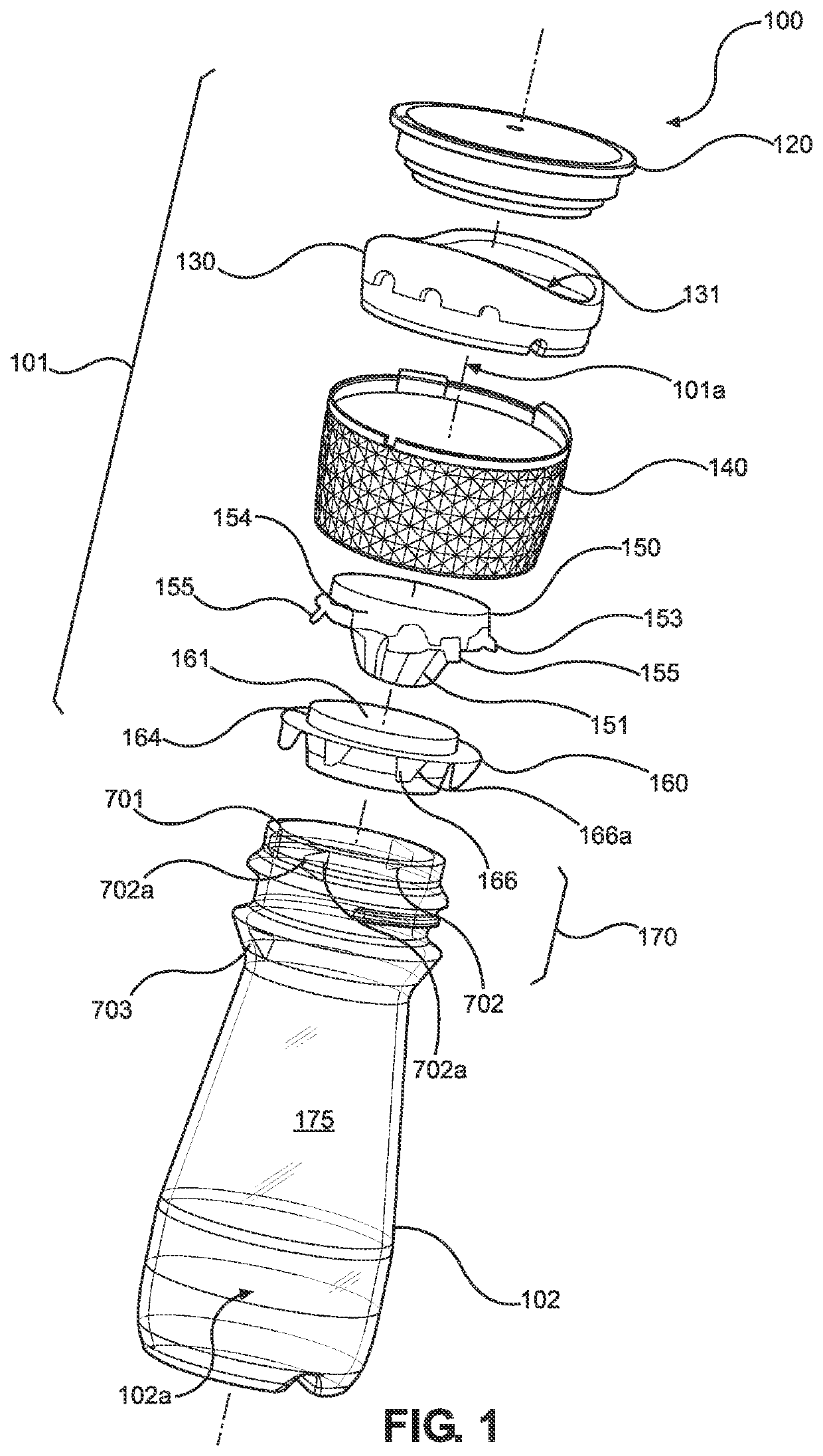
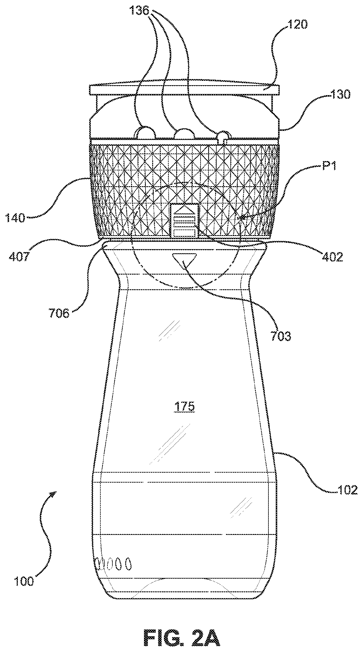
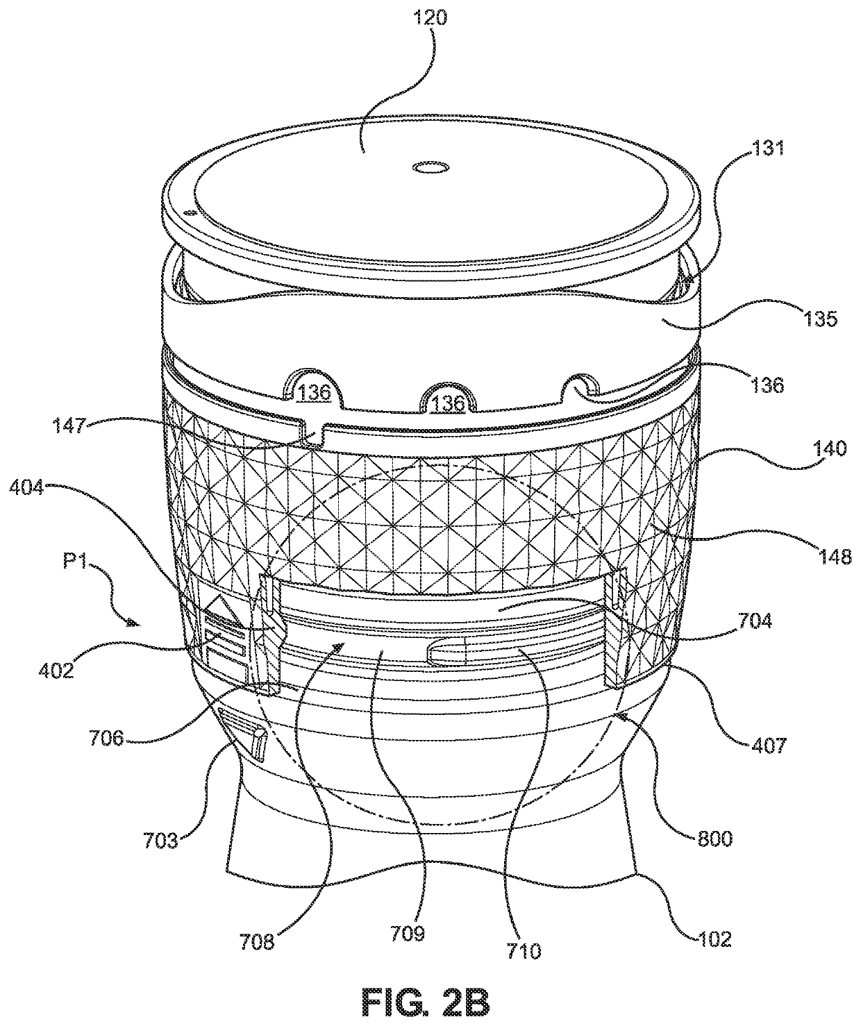
The patent text describes a closure design for a grinder that prevents waste, allows easy removal and replacement of parts, and promotes recycling. The closure has a secure connection between the cap and the bottle, but can also be easily removed for inspection or refilling. The closure also confirms the secure attachment and is tamper resistant. The design includes a recessed groove with lock beads that prevent the cap assembly from being easily removed from the container. Overall, the closure design improves the user experience and reduces waste.

Problems solved by technology

However, there are drawbacks with such conventional designs.
Additionally, if the cap or the condiment are compromised in some manner (e.g., if a crack forms in the cap that prevents grinding from being performed or permits undesirable foreign bodies such as moisture, dirt, dust, other substances to infiltrate and contaminate the grinder), the only solution is to discard the defective grinder and replace it with a new one.
With respect to removable closure-designs, such as the male and female threaded arrangements, it is difficult to visually confirm secure attachment and / or detect tampering.
Additionally, the illustrations are merely representational and may not be drawn to scale.

Method used


Image

  • Grinder device
  • Grinder device
  • Grinder device

Examples


Embodiment Construction

[0044]The particulars shown herein are by way of example and for purposes of illustrative discussion of the various embodiments of the present invention only and are presented for purposes of providing what is believed to be the most useful and readily understood description of the principles and conceptual aspects of the invention. In this regard, no attempt is made to show details of the invention in more detail than is necessary for a fundamental understanding of the invention, the description making apparent to those skilled in the art how the several forms of the invention may be embodied in practice.

[0045]The present invention will now be described by reference to more detailed embodiments. This invention may, however, be embodied in different forms and should not be construed as limited to the embodiments set forth herein. Rather, these embodiments are provided so that this disclosure will be thorough and complete, and will fully convey the scope of the invention to those ski...


PUM


Abstract

A grinder device is provided. The grinder device may include a container, a cap assembly configured to be friction-fit to the container such that the cap assembly is removably lockable to the container, and a grinding mill disposed within the cap assembly to perform a grinding operation of condiment disposed in the container. The grinding mill may include a movable grinder portion and a fixed grinder portion that are rotatable relative to each other, and the fixed grinder portion is engagable with the container to permit relative rotation between the cap assembly and the container.

Description

CROSS-REFERENCE TO RELATED APPLICATIONS[0001]This application claims priority benefit from U.S. Provisional Application No. 63 / 147,621, filed Feb. 9, 2021, which is hereby incorporated by reference in its entirety.TECHNICAL FIELD[0002]The present disclosure generally relates to the field of spice grinders and closures for such grinders.BACKGROUND[0003]Several types of grinders for grinding condiments, such as pepper, salt, and berries, are known. For example, a conventional grinding device may include a bottle to store the un-ground condiment and a cap attached to the bottle where the cap incorporates therein a mill for grinding the condiment. While some caps are known to be attached, in the traditional sense, to an upper end of the bottle, other caps are known to have a configuration in which the cap serves as a base support for the grinder device. Closure systems for such grinding devices are also known. The closure systems can be non-removable one-way snap-fit or friction-fit arr...

Claims


Application Information

Patent Timeline
IPC IPC(8): A47J42/04A47J42/38
CPCA47J42/04A47J42/38
Inventor LE ROUX, MORGANRATTIN, OLIVIER
Owner MCCORMICK & CO INC
Learn More