Fall protection system

a technology for safety devices and fall protection, which is applied in the direction of safety belts, constructions, buildings, etc., can solve the problems of difficulty in maintaining the fall protection system in compliance with safety operational requirements, and the difficulty in installing the system on the vertical ladder, so as to minimize any undesired structure, reduce the risk of falling, and reduce the effect of falling

Pending Publication Date: 2022-08-18
FORMETCO
View PDF0 Cites 0 Cited by
  • Summary
  • Abstract
  • Description
  • Claims
  • Application Information

AI Technical Summary

Benefits of technology

[0006]Described herein is fall protection system and a method of using a fall protection system. In one aspect, the fall protection system of the present invention provides a fall protection system having an efficient simple design that permits a user to quickly and easily attach the fall protection system to a desired portion of the substantially vertical wall or ladder, which is fixedly attached to an associated structure. In one aspect, portions of the fall protection system utilized the load placed on a portion of the ladder to fix the fall protection system relative to the ladder. In a further aspect, the fall protection system minimizes any undesired structure that extends on the operator used side of the vertical ladder.

Problems solved by technology

However, if the movement in the downward direction is too fast, which indicates a possible fall event, the fall protection device will operate to grip or contact the cable and brake or stop movement in the downward direction, thereby protecting the person from falling and potentially harming themselves.
One drawback of known fall protection systems that include cables is the difficulty in installing the system on the vertical ladder and the associated difficulty in maintaining the fall protection system in compliance with safety operational requirements.

Method used


Image

  • Fall protection system
  • Fall protection system
  • Fall protection system

Examples


first embodiment

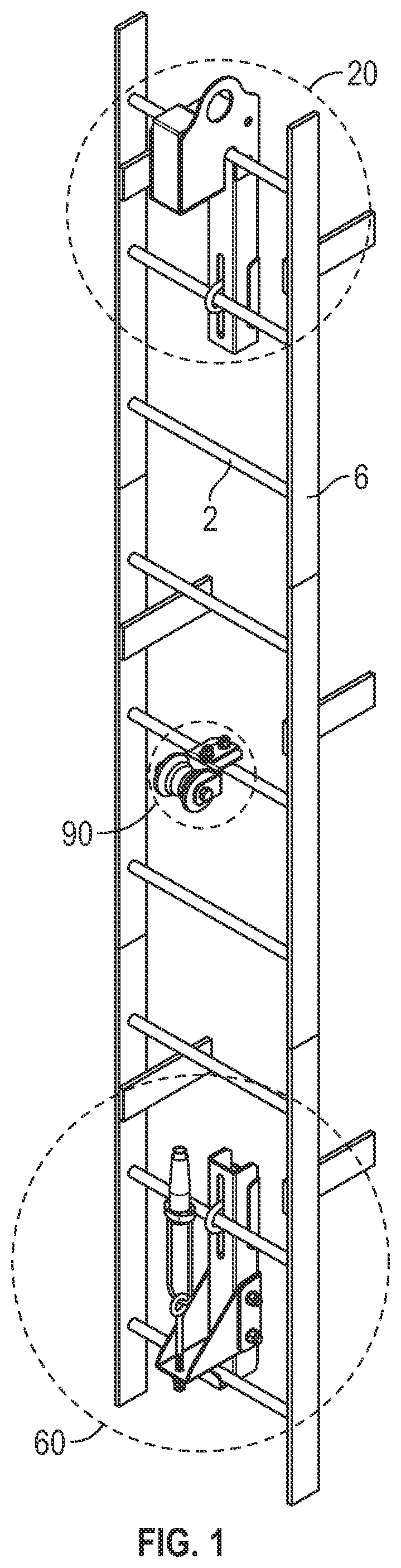
[0067]Referring now to FIGS. 8-10, the bottom bracket assembly 60 can comprise an elongated vertical member 62 and a horizontal member 70 that that is integrally coupled to the vertical member. The horizontal member 70 extends outwardly therefrom the vertical member 62 and defines an opening 72 that is configured to accept an eye bolt 74 having an elongated shaft and a threaded end. A horizontally extending lip 63 can be connected to the lower end of the vertical member 62 and form a J-shape in cross-section to allow the bottom bracket assembly 60 to connect to a portion of a rung of the ladder. In a further aspect, a second conventional automatic cable connector 76, such as described above, can be conventionally coupled to the distal end of the eyebolt 74.

[0068]The upper portion of the elongated vertical member 62 can define an elongated slot 66 that extends substantially vertically. This slot 66 is configured to accept the ends of a U-shaped coupling device 68.

[0069]In operation, ...

second embodiment

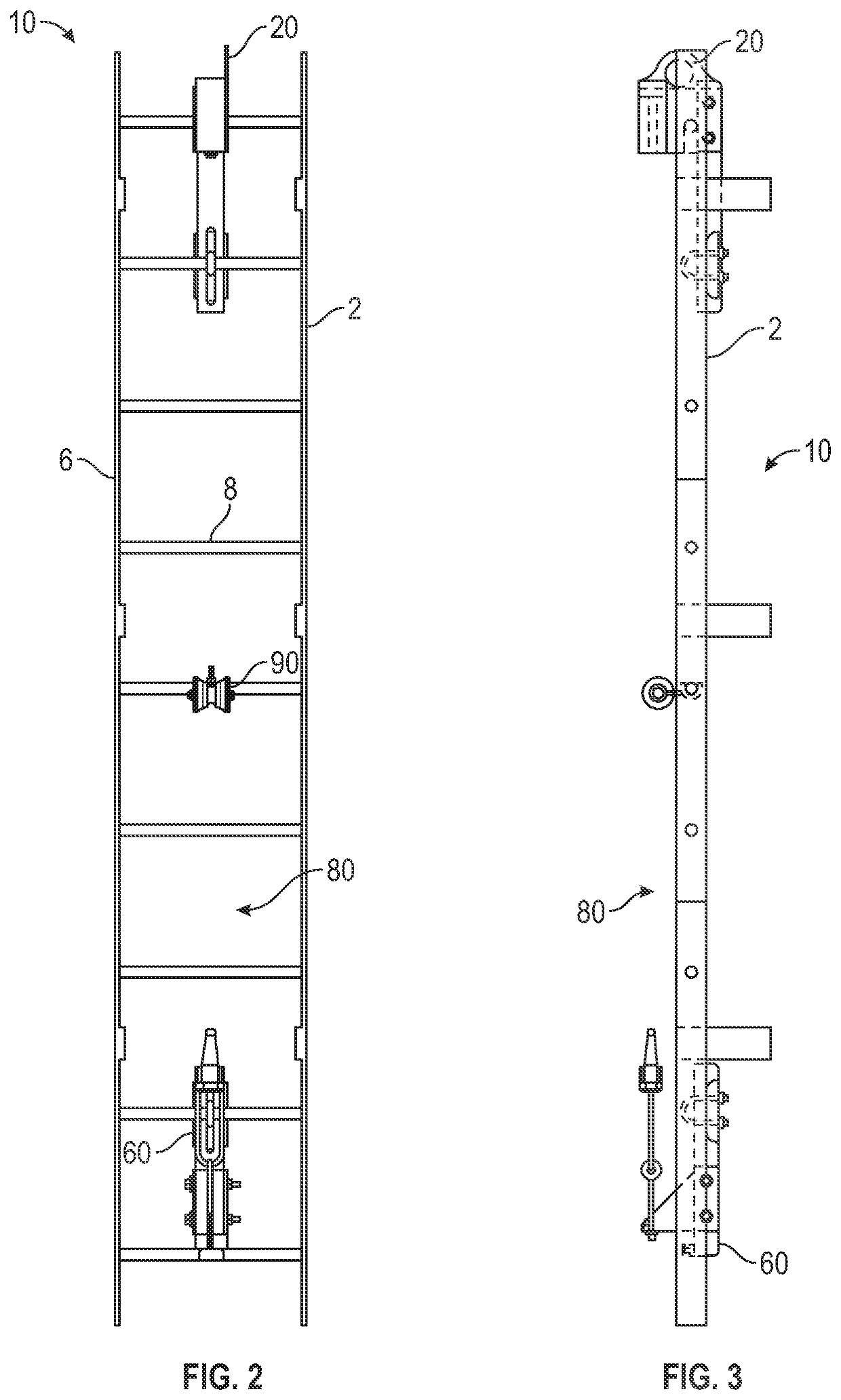
[0074]Referring to FIGS. 17-19, the fall protection system 10 that is fixedly mountable to a vertical ladder is shown. In this aspect, the top and bottom bracket assemblies 20′, 60′ are configured to fixedly mount to the ladder and aid in stabilizing the cable that extends under tension therebetween. The top bracket assembly 20′ can be mountable to a top portion of the ladder, the spaced bottom bracket assembly 60′ can be mountable to a bottom portion of the ladder, and, in used, the cable guide 90′ can be mountable to the ladder between the respective top and bottom bracket assemblies.

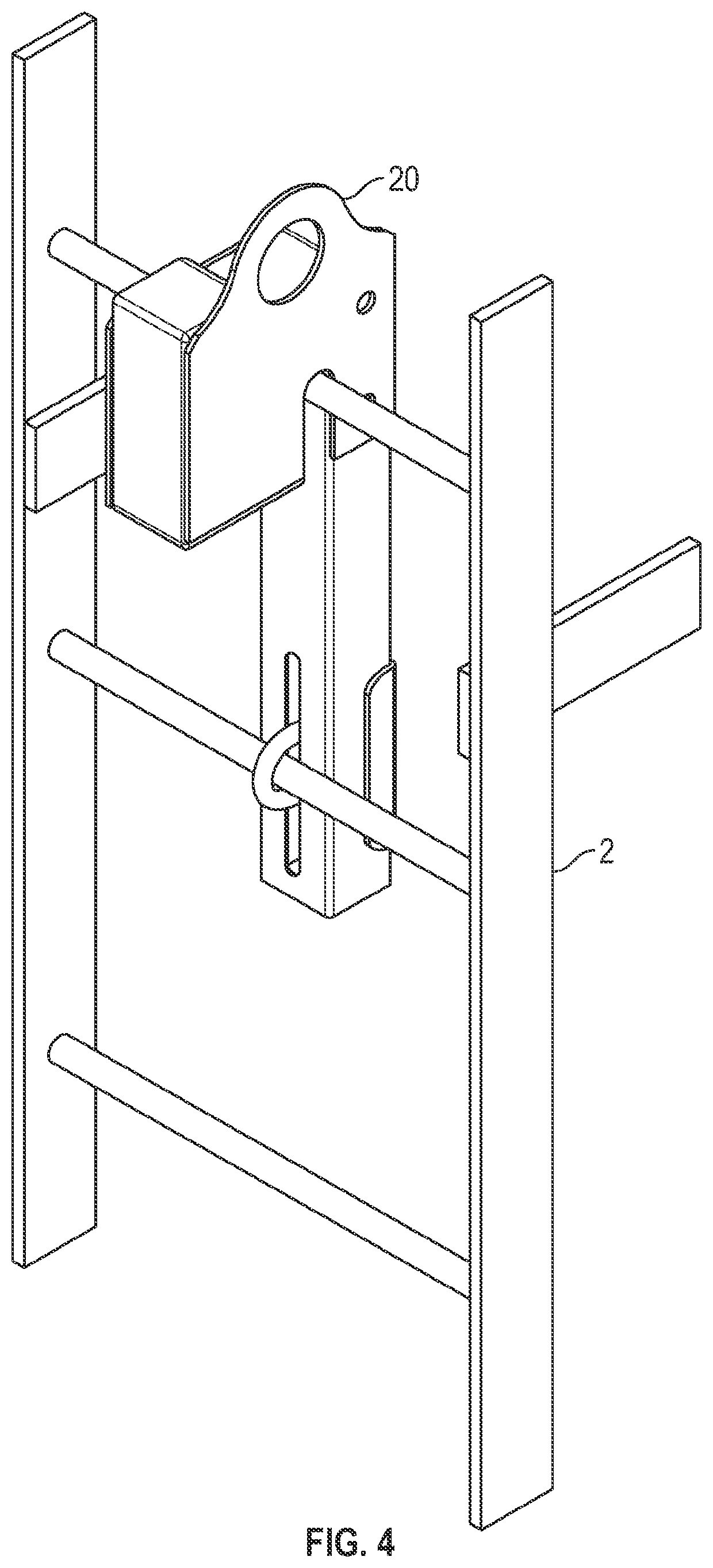
[0075]In one aspect, and as shown in FIGS. 20-23, the top bracket assembly 20′ can comprise an elongated vertical member 122 having a lower portion 123 and an upper portion 124 and a horizontal member 126 that has a proximal portion 127 that is integrally coupled to the upper portion 124 of the vertical member. The horizontal member 126 extends outwardly therefrom the upper portion 24 of the vertical ...


PUM


Abstract

A fall protection system having a top bracket assembly that is mountable to a top portion of the ladder, a spaced bottom bracket assembly that is mountable to a bottom portion of the ladder, and a cable extending therebetween portions of the top bracket assembly and the bottom bracket assembly substantially parallel to a plane bisecting the vertical ladder at a desired distance from the plane.

Description

CROSS-REFERENCE TO RELATED APPLICATIONS[0001]This application is a continuation of U.S. patent application Ser. No. 16 / 208,868, filed Dec. 4, 2018, which claims the benefit of U.S. Provisional Patent Application No. 62 / 594,050, filed on Dec. 4, 2017; and U.S. Provisional Patent Application No. 62 / 623,803, filed on Jan. 30, 2018.INCORPORATION BY REFERENCE[0002]The disclosure of U.S. patent application Ser. No. 16 / 208,868, filed Dec. 4, 2018, U.S. Provisional Patent Application No. 62 / 594,050, filed on Dec. 4, 2017; and U.S. Provisional Patent Application No. 62 / 623,803, filed on Jan. 30, 2018, are hereby incorporated by reference for all purposes as if presented herein in their entirety.FIELD OF THE INVENTION[0003]The present invention relates generally to fall protection safety devices and, in particular, to a fall protection system for use in conjunction with a fall protection device and a ladder cage on the side of a structure.DESCRIPTION OF RELATED ART[0004]There are many structu...

Claims


Application Information

Patent Timeline
Patent Type & Authority Applications(United States)
IPC IPC(8): E06C7/18A62B35/00A62B35/04E06C9/02
CPCE06C7/186A62B35/0037A62B35/04A62B35/0056A62B35/0062E06C9/02A62B35/0068A62B35/0075
Inventor ADAMS, JONATHON CHRISTOPHER
Owner FORMETCO
Why Eureka
Try Eureka