Downhole sealing apparatus and method

Pending Publication Date: 2022-08-25
RUBBERATKINS
View PDF0 Cites 0 Cited by
  • Summary
  • Abstract
  • Description
  • Claims
  • Application Information

AI Technical Summary

Problems solved by technology

There remains drawbacks with existing sealing assemblies, fo

Method used


Image

  • Downhole sealing apparatus and method
  • Downhole sealing apparatus and method
  • Downhole sealing apparatus and method

Examples


Example

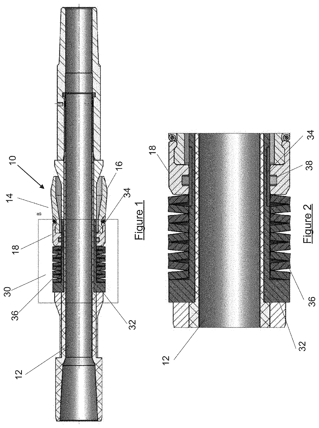
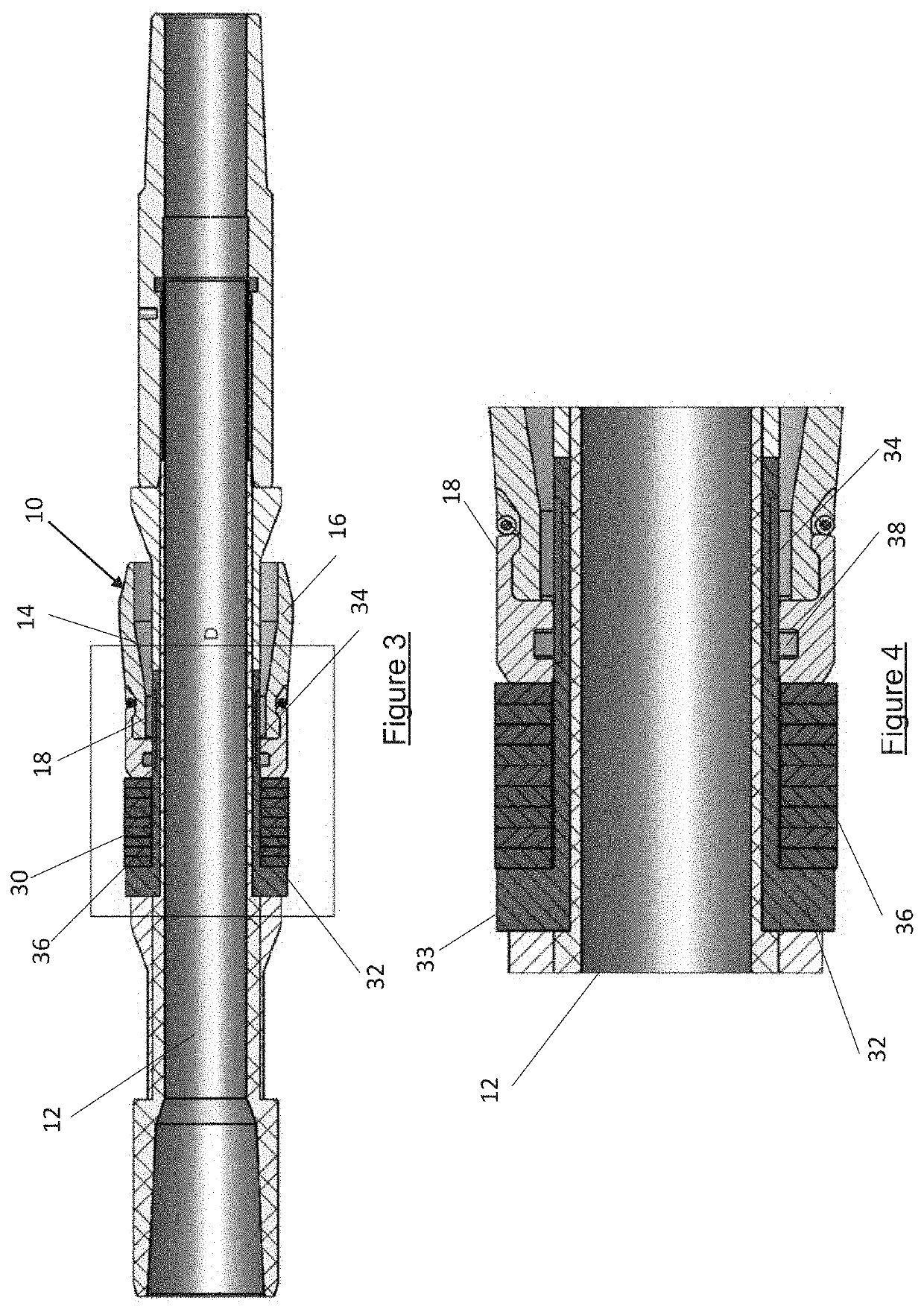
[0048]A downhole sealing apparatus 10 is shown in FIG. 1 of the accompanying drawings. The downhole sealing apparatus 10 comprises a sealing assembly, generally denoted 14, which in the illustrated apparatus 10 is in the form of a cup sealing assembly. The sealing assembly 14 comprises a sealing element 16 and a support member 18. The support member 18 may comprise a seal 38, for example an O-ring, which is provided in an annular groove in the support member 18. It will be appreciated that any form of sealing assembly may be utilised in the downhole sealing apparatus 10, particularly sealing assemblies which form a seal upon exposure to a pressure differential, such as cup sealing assemblies. The sealing assembly 14 is positioned on a mandrel 12 for location downhole.

[0049]The downhole apparatus 10 further comprises a bypass arrangement 30. The bypass arrangement 30 comprises a biasing mechanism in the form of a series of disc springs 36 which bias the downhole sealing apparatus to ...


PUM


Abstract

A downhole sealing apparatus having a sealing assembly with one or more seal elements configured to engage a bore wall or bore-lining tubular wall to seal an annulus between the apparatus and the wall or tubular wall. A bypass arrangement is configured to provide selective bypass of the sealing assembly and the sealing apparatus is reconfigurable between a first configuration permitting bypass of the sealing assembly and a second configuration in which the bypass arrangement prevents or restricts bypass of the sealing assembly. A downhole method provides the downhole sealing apparatus within a bore hole, with the downhole sealing apparatus reconfigured from the first configuration in which the bypass arrangement permits bypass of the sealing assembly to a second configuration in which the bypass arrangement prevents or restricts bypass of the sealing assembly.

Description

CROSS-REFERENCE TO RELATED APPLICATIONS[0001]This application claims priority from Application 2102393.2 filed on Feb. 19, 2021 in the United Kingdom.FIELD OF THE INVENTION[0002]The present disclosure relates to a downhole sealing apparatus and method.BACKGROUND OF THE INVENTION[0003]Sealing assemblies are used extensively in the oil and gas industry for sealing an annulus in a wellbore, such as may exist between a mandrel and a bore wall or bore-lining tubular wall. Typically, sealing is achieved by the use of annular components which are mounted on the mandrel and which extend between the mandrel and the bore wall or bore-lining tubular wall. Such annular sealing components may take a variety of forms, including annular sealing bands, cup seals, inflatable bladders, swellable elements and the like.[0004]In some cases, the sealing assemblies are activated to form the seal between the bore wall or bore-lining tubular wall and the mandrel, for example by the application of flow rate ...

Claims


Application Information

Patent Timeline
IPC IPC(8): E21B33/12E21B47/09
CPCE21B33/1208E21B47/09E21B33/1294E21B33/126E21B33/129E21B33/12E21B33/128E21B33/10E21B33/1285
Inventor ROTHNIE, STUARTGASKIN, KEITH
Owner RUBBERATKINS
Why Eureka
Try Eureka