Drum hoop holding device for a drum pedal

Inactive Publication Date: 2000-01-04
HOSHINO GAKKI COMPANY LIMITED
View PDF3 Cites 34 Cited by
  • Summary
  • Abstract
  • Description
  • Claims
  • Application Information

AI Technical Summary

Problems solved by technology

Such a hoop 106 has a large thickness, which causes the clamp volume of the main hoop clamp body to become heavy.
If the tightening bolt 125 is made longer, however, there is a danger that it may hit the pedal plate 111 reducing the operability of the pedal plate.
In addition, the appearance of the pedal deteriorates.
If the performance is then continu

Method used


Image

  • Drum hoop holding device for a drum pedal
  • Drum hoop holding device for a drum pedal
  • Drum hoop holding device for a drum pedal

Examples


Embodiment Construction

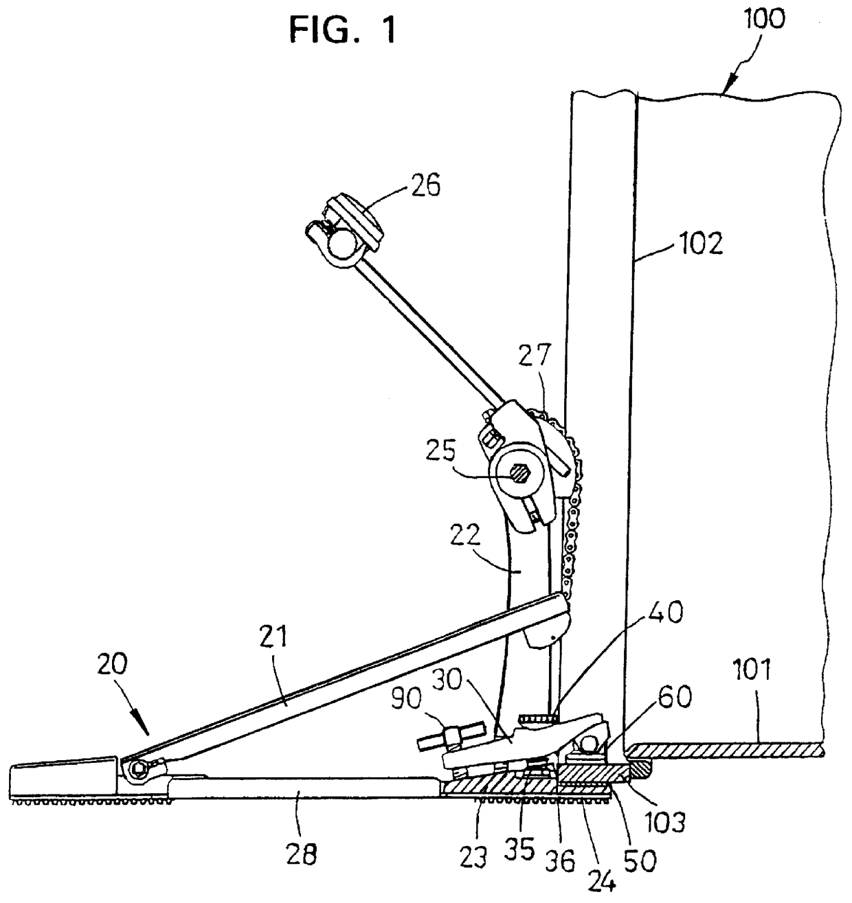
The bass drum 100 shown in FIG. 1 has a structure which is similar to that drum explained above in connection with FIG. 13, including a drum body 101, a drum head 102, and a drum hoop or rim around the body at the drum head.

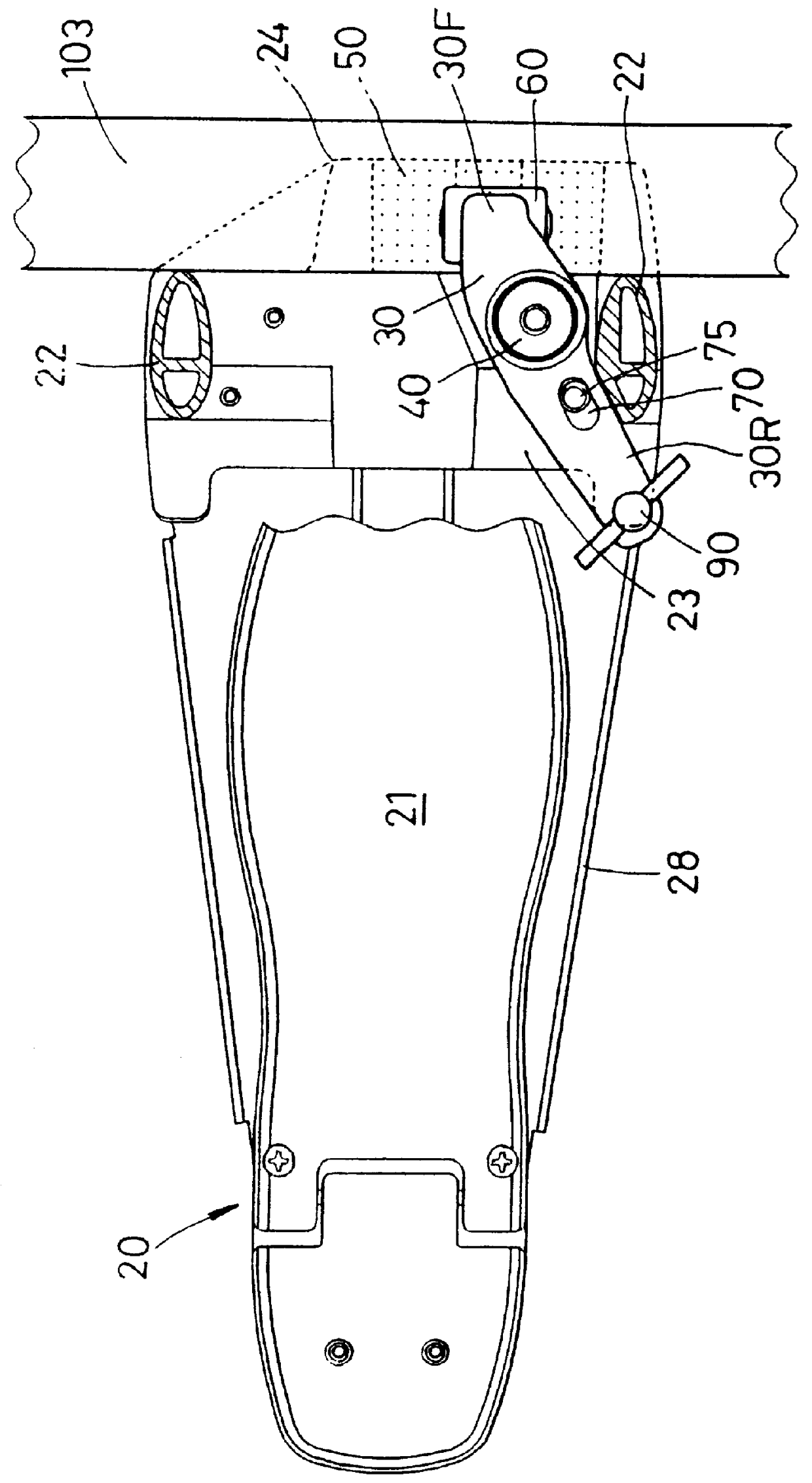
In addition, the drum pedal 20 is also known and includes a pedal plate 21, a support 22 erected on a support base 23, a drum hoop receiver 24 for the front of the support base 23, a rotary shaft 25 for the support 22, a beater 26 installed on the rotary shaft 25, and a chain 27 for rotating the rotary shaft 25 by vertical swinging movement of the pedal plate 21.

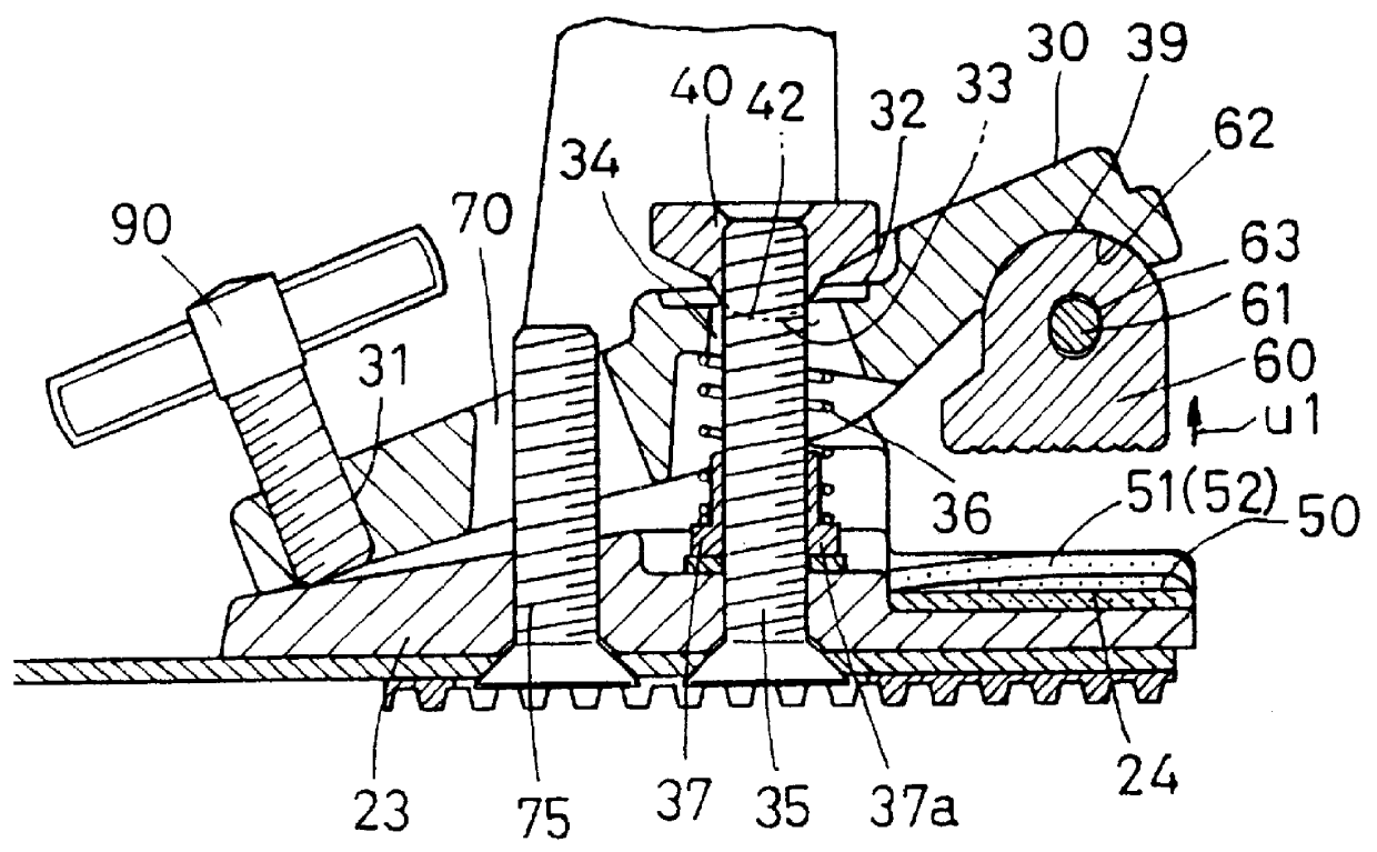
The hoop holding device includes a holding jaw 60 that presses the drum hoop 103 against the hoop receiver 24 at the front of the support base 23. The jaw is on the front of the main hoop clamp body 30 that is supported on the support base of the drum pedal 20. A tightening bolt 90 is screwed through a screw receiving bore (FIG. 3) in the main hoop clamp body 30 for fixing the body.

The support structure f...


PUM


Abstract

The invention relates to a drum hoop holding device for a drum pedal, and the drum pedal includes a pivotal pedal plate. The holding device includes a hoop clamp body with a front part that supports a jaw that clamps the drum hoop against a support base of the pedal. The support base includes an inclined elastic material surface against which the hoop is clamped. The clamp body is oriented so that the front part is below the pedal while the rear part is laterally out from under the pedal. The clamp body has a hole through it, a spring that pushes the clamp body up, a bolt that passes through the hole with a seat atop the clamp body that receives the tightening nut and the curvature of the seat in the top of the clamp body cooperates with the curvature of the surface of the nut to permit orientation of the clamp body according to the thickness of the drum hoop to the clamp. A tightening bolt at the rear of the clamp body tightens the jaw at the front of the clamp body against the drum hoop.

Description

This invention relates to a drum hoop holding device for a drum pedal.PRIOR ART EMBODIMENTAn example of a hoop holding device for the hoop of a bass drum according to one prior art embodiment is shown in FIGS. 13 through 15. This structure is disclosed in the publication of Japanese Utility Model No. Hei 4-96794, which corresponds to U.S. Pat. No. 5,185,489. It includes a holding jaw 122 that presses the drum hoop 103 between the front part of the main hoop clamp body 120, which is freely rotatably supported in the front and rear directions through the shaft 121, and the drum hoop receiving part 114 at the front of the support base 113 of the drum pedal 110. A tightening bolt 125 fixes the main hoop claim body 120 by being screwed through the screw threaded opening in the rear part 126 (FIG. 14) of the main hoop claim body.In addition, the holding jaw 122 is freely rotatably held in the front and rearward directions by a cross shaft 123 on which the jaw pivots.The drum pedal 110 for...

Claims


Application Information

Patent Timeline
IPC IPC(8): G10D13/00
CPCG10D13/006G10D13/11
Inventor HOSHINO, YOSHIHIRO
Owner HOSHINO GAKKI COMPANY LIMITED
Why Eureka
Try Eureka