Firearm, particularly a revolver pistol

a revolver and pistol technology, applied in the field of revolvers, can solve the problems of large drums, inability to reduce inconvenience, and damage to parts of revolvers, and achieve the effect of reducing inconvenience by introducing a shock absorption spring between the moving parts

Inactive Publication Date: 2000-01-25
GHISONI EMILIO
View PDF6 Cites 21 Cited by
  • Summary
  • Abstract
  • Description
  • Claims
  • Application Information

AI Technical Summary

Benefits of technology

Another of the invention is to provide a revolver having a third type action by comparison with conventional revolvers.
A further object of the invention is to provide a revolver that in case of defective cartridge, simply allows pulling of the trigger again (DA) or to re-cocking of the hammer (SA) to keep firing.
The above aims, and other aims. These and other objects that will become apparent to those skilled in the art, are achieved by a revolver firearm comprising a body divided into an upper part, or slider, comprising a barrel and a drum, and a lower part, or case, comprising a handle, a trigger and a hammer on which the upper part is slidable. At least a first kinematic means is arranged in the case for arming the hammer. At least a second kinematic means is arranged in said sliding slider and is adapted to cause the rotation of the drum and to successively align the firing chambers of said drum with the barrel, the first and second kinematic means are selectively activated by manually operating directly the hammer or the trigger or using the forces generated by the recoil. Third kinematic means connects the first means to the second means. The kinematic means comprising a desmodromic member having an active transfer action synchronously transferring motion from the first means to the second means during the firing action and a resistance passive action during the automatic re-cocking of the firearm caused by the recoil forces.
will be more apparent by the following description of an embodiment of the invention, illustrated, by way of example in the accompanying drawings in which:

Problems solved by technology

A first drawback of such automatic revolver is that the rotation of the drum occurs at recoil and is consequently violent and can cause damage to parts of the revolver.
An attempt to reduce such inconvenience by inserting a shock absorbing spring between the moving parts has not been successful.
A first drawback is that the drum has a considerable size and the second drawback is that it is impossible to rotate the drum without moving the two parts of the firearm.
This second drawback is particularly severe.
In the case of a defective cartridge, it is impossible to take advantage of the typical feature of revolvers that simply allow a pull of the trigger to fire another round.

Method used


Image

  • Firearm, particularly a revolver pistol
  • Firearm, particularly a revolver pistol
  • Firearm, particularly a revolver pistol

Examples


Embodiment Construction

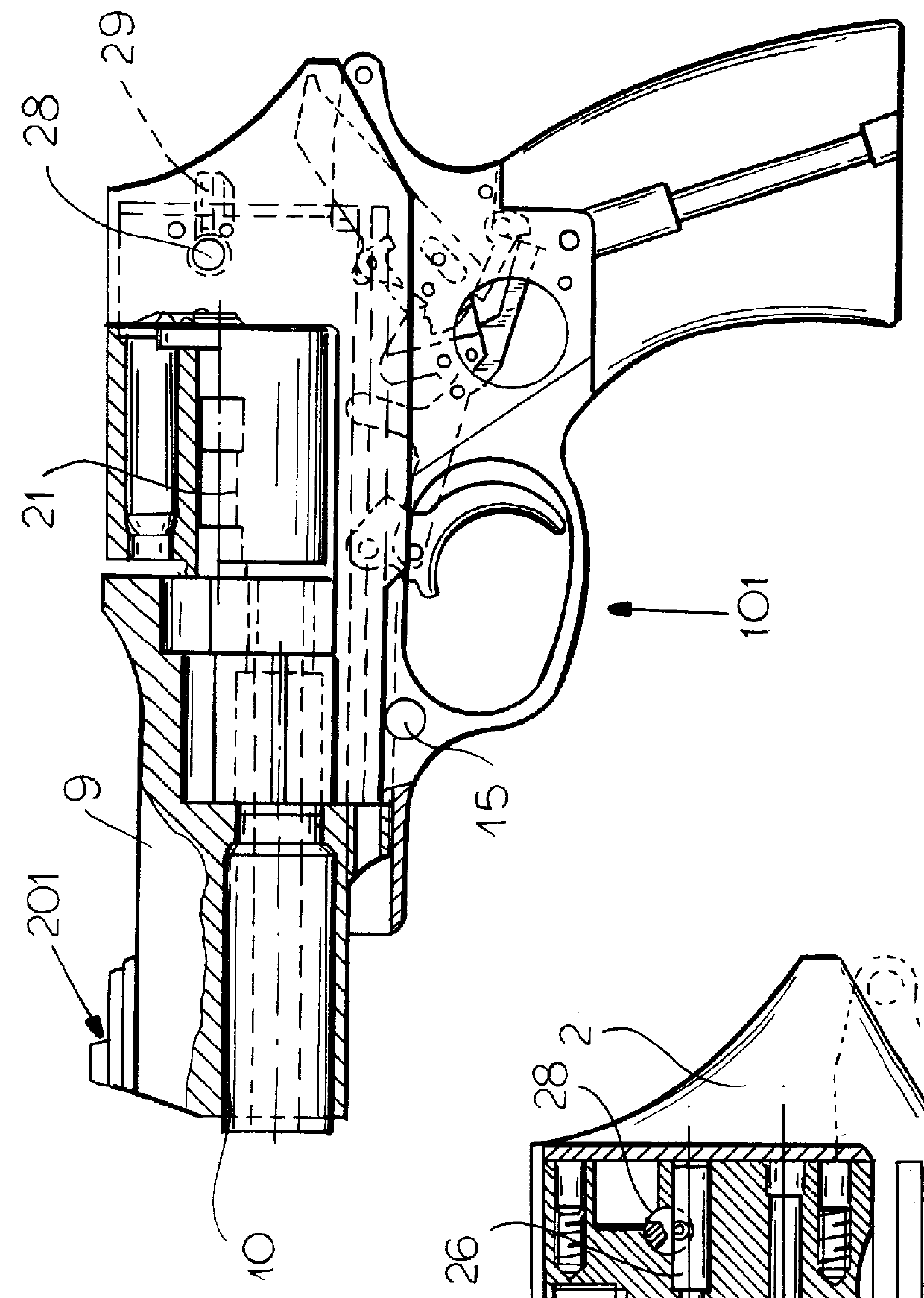
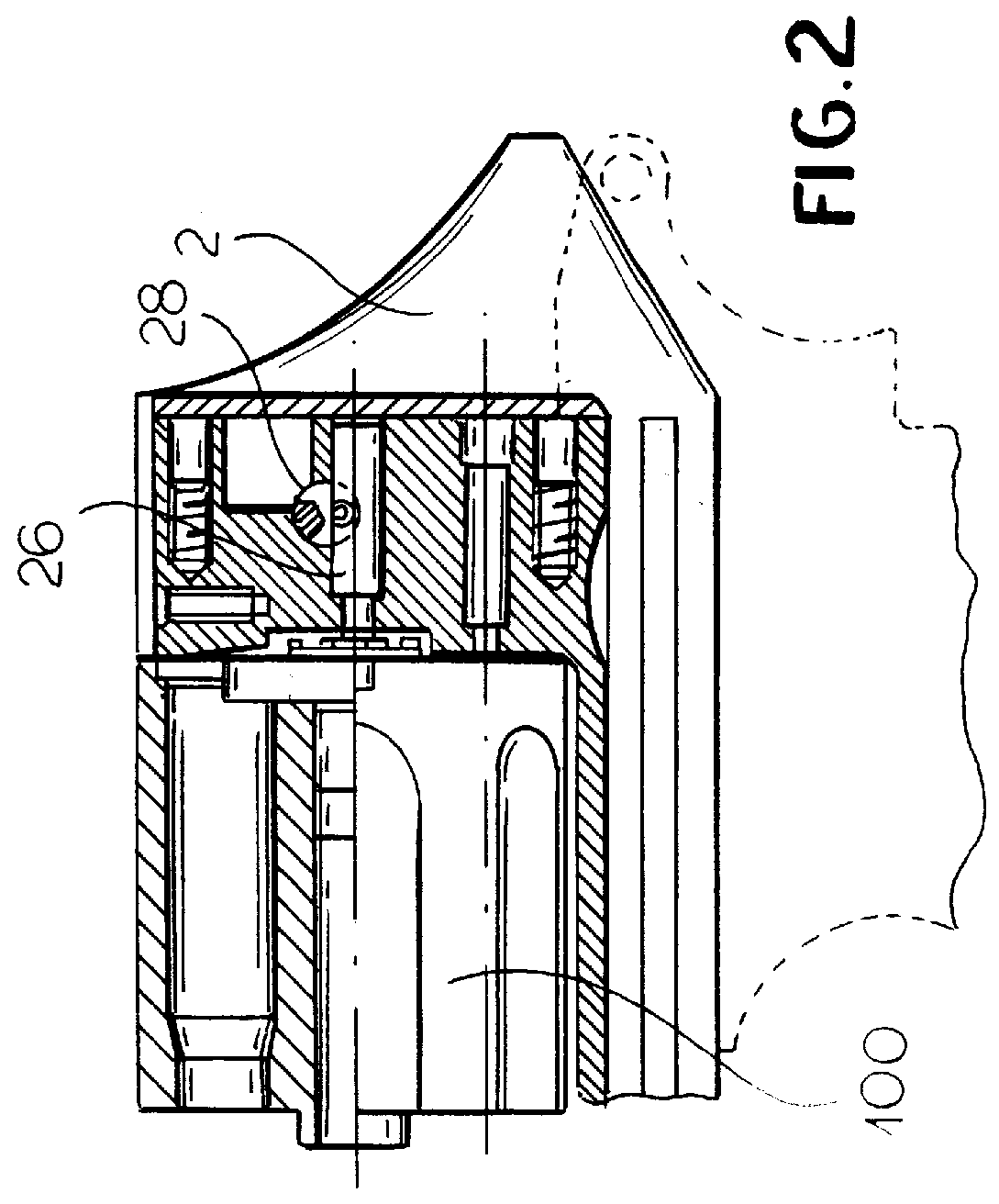
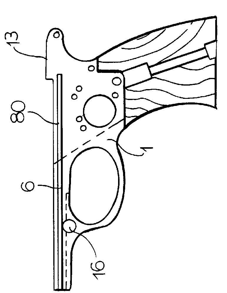
The revolver according to the invention, generally designated by the reference numeral 101, comprises a case 1 and a slider 2 mobile on guides 80 (FIG. 3) with respect to the case and biased to its original position by a spring 3 wound on a spring guide 4 resting, with its base 5, on a pin 6 planted in the case.

At the front, the spring guide 4 is freely arranged in a hole 7 of an appendix 8 of the guard 9. The guard 9 is received between the barrel 10 and the slider 2, wherein the barrel is screwed, by means of the step formed by the different diameters of the barrel.

A washer 11 is arranged at the site of contact between the guard and the barrel and has the following function: by varying the thickness of the washer 11, for example using washers of different thickness, the critical distance between barrel and drum can be varied, thus providing for the use of barrels of different length in the revolver.

The run of slider-barrel-guard assembly is stopped backwards by teeth 13 constitute...


PUM


Abstract

Revolver firearm comprising a body divided in an upper part, or slider, comprising a barrel and a drum, slidingly associated with a lower part, or case, comprising a handle, a trigger and a hammer; a first kinematic chain arranged in said case for arming the hammer; a second kinematic chain, arranged in said slider, and adapted to cause the rotation of the drum and to successively align the firing chambers of the drum with the barrel, the first and second kinematic chains being selectively activated by manually operating the hammer directly or the trigger or using the forces generated by the recoil; a third kinematic chain for connecting the first and second chains; the third kinematic chain has a desmodromic member having an active transfer action synchronously transferring motion from the first chain to the second chain during the firing action and a resistance passive action during the automatic re-cocking of the firearm caused by the recoil forces.

Description

The present invention relates to a firearm, particularly a revolver pistol.The need of an automatic revolver has always been felt. Fosbery was the first one to modify the revolver of Webley to make it automatic. In the Webley-Fosbery revolver, the body of the weapon is divided in two parts associated by means of sliders and free to move relatively to a certain extent. The upper part of the weapon, which comprises the barrel, cylinder and hammer, in reaction to the shot, moves back with respect of the lower part, which is constituted by the handle and by the trigger support. During this backward motion, the hammer is forced to rotate because its rear part abuts against an inclined plane of the lower part of the body. A lever connected to the hammer acts against the teeth of the drum causing it to rotate. A first drawback of such automatic revolver is that the rotation of the drum occurs at recoil and is consequently violent and can cause damage to parts of the revolver.An attempt to ...

Claims


Application Information

Patent Timeline
Patent Type & Authority Patents(United States)
IPC IPC(8): F41A19/00F41A19/52F41C3/14F41C3/00
CPCF41A19/52F41C3/14
Inventor GHISONI, EMILIO
Owner GHISONI EMILIO
Why Eureka
Try Eureka