Vane-airfoil combination

a technology of airfoil and combination, which is applied in the field of airfoils, can solve the problems of parasitic drag, force accompanied by drag force, and massey does not teach or suggest utilizing a plurality of vanes to achieve the effect of diversion of airflow

Inactive Publication Date: 2000-04-04
PARRISH IV OVERTON L
View PDF20 Cites 18 Cited by
  • Summary
  • Abstract
  • Description
  • Claims
  • Application Information

AI Technical Summary

Problems solved by technology

However, with this lifting force is accompanied a drag force.
Parasitic drag is created by the disruption of the flow of air around the airfoil's surfaces.
Although Massey discloses diverting the airflow about the airfoil, Massey does not teach or suggest utilizing a plurality of vanes to achieve this diversion of airflow.
Additionally, Massey does not show rotating an airfoil's lift or drag forces to a different direction.
Although Orr discusses diverting the airflow over the airfoil, Orr does not teach or suggest utilizing a plurality of vanes to divert the air

Method used


Image

  • Vane-airfoil combination
  • Vane-airfoil combination
  • Vane-airfoil combination

Examples


first embodiment

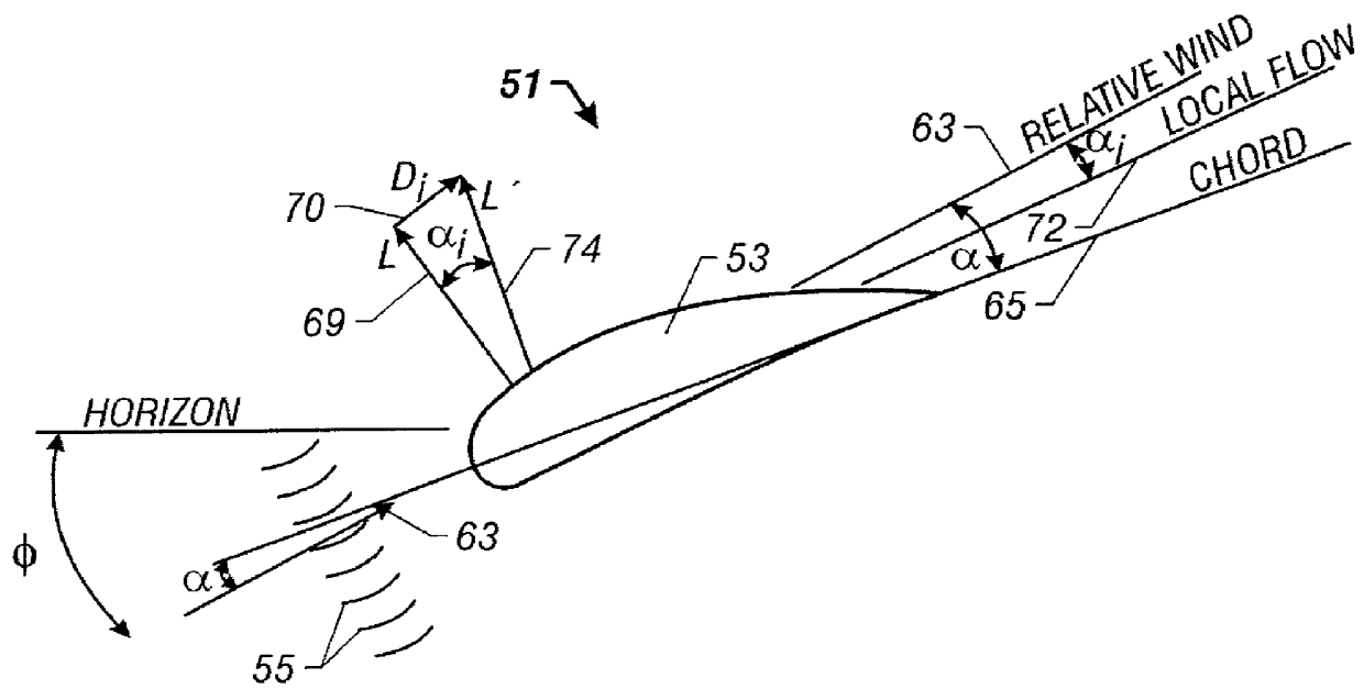
FIG. 3 is a side view of a vane-airfoil combination 51 illustrating the forces upon the vane-airfoil combination 51 according to the teachings of the present invention. The vane-airfoil combination 51 includes an airfoil 53 and a plurality of vanes 55. The vane-airfoil combination 51 travels with a forward velocity through a fluid, such as an airflow 57. The direction of the airflow 57 is a relative wind 59 and, as illustrated for simplicity, is parallel to the horizon. The airfoil 53 is rotated downwardly with an orientation angle .phi. in relation to the horizon. The plurality of vanes 55 is located in front of a leading edge 61 of the airfoil 53. Although FIG. 3 depicts the plurality of vanes 55 slightly below a leading edge of the airfoil 53, the plurality of vanes 55 may be positioned at other locations in front of the airfoil 53 to achieve different changes in the direction of flow of the airflow. The plurality of vanes 55 must only encounter the airflow 57 prior to the airfoi...

second embodiment

FIG. 5 is a side view of a vane-airfoil combination 81 having a fore-body 83 and an after-body 85 according to the teachings of the present invention. The vane-airfoil combination 81 includes an airfoil 87, a plurality of vanes 89, the fore-body 83 and the after-body 85. The vane-airfoil combination 81 operates through a fluid, such as an airflow 91, in a similar manner as described for the vane-airfoil combination 51, in a direction opposite a relative wind 93 which is, for simplicity, is parallel to the horizon.

However, the airfoil combination 81 includes the fore-body 83 positioned directly in front of the airfoil 87, as in relation to the oncoming airflow 91. The vane-airfoil combination 51 (FIG. 3) may create a high pressure region on the airfoil 53, especially at very high or low angles of attack. The addition of the fore-body 83 provides a means for deflecting any oncoming airflow 91 from hitting the airfoil 87 at an undesirable angle (negative angle of attack). The fore-body...

third embodiment

FIG. 7 is a side view of a vane-airfoil combination 121 in the present invention. In this embodiment, a rotating cylinder 123 is utilized as the primary airfoil. The vane-airfoil combination 121 includes a plurality of vanes 125, and an optional fore-body 127. The fore-body 127 may be constructed as a cockpit or cabin for carrying passengers or cargo in an aircraft.

The rotating cylinder 123 rotates about a center axis of the rotating cylinder 129 by a mechanism, such as an engine, providing a rotation as illustrated in FIG. 6. The rotating cylinder 123 travels through a fluid, such as an airflow 131 in a direction opposite of a relative wind 133. The plurality of vanes 125, located forward of the rotating cylinder 123, diverts the airflow 131 across the rotating cylinder 123 to a new relative wind 135. Since the airflow 131 now encounters the rotating cylinder 123 from a different direction, forces associated with the rotating cylinder are shifted to a different direction.

As depicte...


PUM


Abstract

A vane-airfoil combination for shifting forces associated with an airfoil. The vane-airfoil combination includes an airfoil moving through a fluid, such as air. A plurality of vanes is positioned in front of the airfoil to divert the path of the fluid to the airfoil. The change in the path of the fluid rotates the forces associated with the airfoil in relation to the original path of the fluid. Specifically, a lift force is rotated to provide a thrust component force, as well as a lift component force. In addition, a drag force is rotated to provide a lift component force, as well as a reduced drag component force. The airfoil may be any type of airfoil, such as a rotating cylinder. The vane-airfoil combination may also include a fore-body and an after-body for reducing the pressure along an upper portion of the airfoil.

Description

1. Technical Field of the InventionThis invention relates to airfoils, and more particularly, to an airfoil utilizing vanes to divert an oncoming airflow onto the airfoil.2. Description of Related ArtAirfoils have been in use for many years on such vehicles as airplanes, automobiles, and boats. Airfoils are used to produce lift by traveling through the air. However, with this lifting force is accompanied a drag force. Many different designs of airfoils have been developed to increase the lifting force, as well as decrease the drag force of the airfoil. The drag force of an airfoil is broadly classified as either parasitic drag or induced drag. Parasitic drag includes all drag created by the airfoil, except that drag directly associated with the production of lift. Parasitic drag is created by the disruption of the flow of air around the airfoil's surfaces. Induced drag is the main by-product of the production of lift. It is directly proportional to the angle of attack of the wing an...

Claims


Application Information

Patent Timeline
IPC IPC(8): B62D37/00B62D37/02
CPCB62D37/02
Inventor PARRISH, IV, OVERTON L.
Owner PARRISH IV OVERTON L
Why Eureka
Try Eureka