Oil-cooled type screw compressor

Inactive Publication Date: 2000-04-04
KOBE STEEL LTD +1
View PDF8 Cites 45 Cited by
  • Summary
  • Abstract
  • Description
  • Claims
  • Application Information

AI Technical Summary

Problems solved by technology

As a result, the portion of the oil separating element 47 through which the compressed gas can pass becom

Method used


Image

  • Oil-cooled type screw compressor
  • Oil-cooled type screw compressor

Examples


Embodiment Construction

An embodiment of the present invention will be described in detail hereinunder with reference to the accompanying drawings.

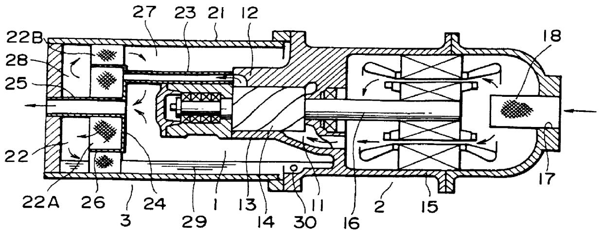
FIG. 1 illustrates an oil-cooled type screw compressor embodying the present invention, which compressor comprises a compressor body 1, a motor 2 and an oil separating / recovering section 3.

The compressor body 1 is of a well-known structure in which a body casing 13 is formed with a suction port 11 on one side and a discharge port 12 on the other side, and a pair of male and female screw rotors 14 (only one is shown in the figure) meshing with each other are accommodated rotatably within the body casing 13.

The motor 2 has a motor casing 15 integral with the body casing 13, and an output shaft 16 thereof also serves as a rotor shaft of one screw rotor 14 to drive the screw rotor. A through hole 17 for the suction of gas is formed in the end face of the motor casing 15 on the side opposite to the compressor body, and a suction filter 18 is fitted in the through hol...


PUM


Abstract

An oil-cooled type screw compressor capable of improving the oil separating efficiency is provided. The oil-cooled type screw compressor includes an outer casing 21 which encloses at least a bearing portion on a discharge port 12 side of a compressor body 1 in an isolated state from a suction port 11, an oil separating element 22 which comprises an inside portion 22A and an outside portion 22B partitioned from each other by an annular partition plate 26 and which bisects the inside space of the outer casing into a space 27 on the compressor body side and a space 28 on the side opposite to the compressor body, a first discharge pipe 23 which conducts a compressed gas discharged together with oil from the discharge port 12 to the inside portion 22A, a shielding plate 24 for isolating the inside portion 22A from the compressor body-side space 27, and a second discharge pipe 25 extending through both the oil separating element 22 and the portion of the casing 21 which covers the space 28 on the side opposite to the compressor body, to conduct the compressed gas which has entered the compressor body-side space 27 from the opposite-side space 28 to the exterior.

Description

1. Field of the InventionThe present invention relates to an oil-cooled type screw compressor in which at least a discharge port-side portion of a compressor body is positioned within a casing with an oil separating element received therein.2. Description of the Prior ArtHeretofore, such an oil-cooled type screw compressor as shown in FIG. 2 has publicly been known. In this known compressor, a motor 42 as drive means for screw rotors 41 has a shaft 43 in common with one screw rotor 41, and a body casing 44 which houses the screw rotors 41 therein and a motor casing 45 of the motor 42 are formed integrally with each other (Japanese Patent Laid Open No. 184984 / 85). In FIG. 2, gas is sucked in through a suction port 46 formed in the left end face of the motor casing 45, then passes through a clearance formed between a stator and a rotor of the motor 42, then is compressed by the screw rotors 41 while being oiled, and passes through an oil separating element 47 for the separation of oil...

Claims


Application Information

Patent Timeline
IPC IPC(8): F04C29/02F04C23/00F04C18/16
CPCF04C29/026F04C23/008F04C18/16Y10S418/01
Inventor TSUBOI, NOBORUSUZUKI, KATSUYUKIUTSUNO, HIDEOMORISAWA, YOSHITAKA
Owner KOBE STEEL LTD
Why Eureka
Try Eureka