Automatic balancing mechanism for medical stand apparatus

a technology of automatic balancing and medical stand, which is applied in the field of automatic balancing mechanism for use with medical stand apparatus, can solve the problems of losing weight balance, failing to retain the operating microscope at the desired spatial position, and not being able to achieve the desired spatial position of the operating microscope, etc., and can solve the problem that my previous invention is not so satisfactory, and the balancing adjustment will hardly be automated unless

Inactive Publication Date: 2000-04-18
MITAKA KOHKI
View PDF13 Cites 86 Cited by
  • Summary
  • Abstract
  • Description
  • Claims
  • Application Information

AI Technical Summary

Problems solved by technology

Otherwise, when the parallel link mechanism is biased, the weight balance will be lost and fail to retain the operating microscope at the desired spatial position.
However, either manner would be realized by a complicated bulky system, which will be undesirable.
My previous invention is actually not so satisfactory because the balance is manually adjusted in spite of its simpler construction than that of any other prior art.
The balancing adjustment will hardly be automated unless modified and thus neither simpler balance adjustment nor minimization of the involving time could be achieved.

Method used


Image

  • Automatic balancing mechanism for medical stand apparatus
  • Automatic balancing mechanism for medical stand apparatus
  • Automatic balancing mechanism for medical stand apparatus

Examples


Embodiment Construction

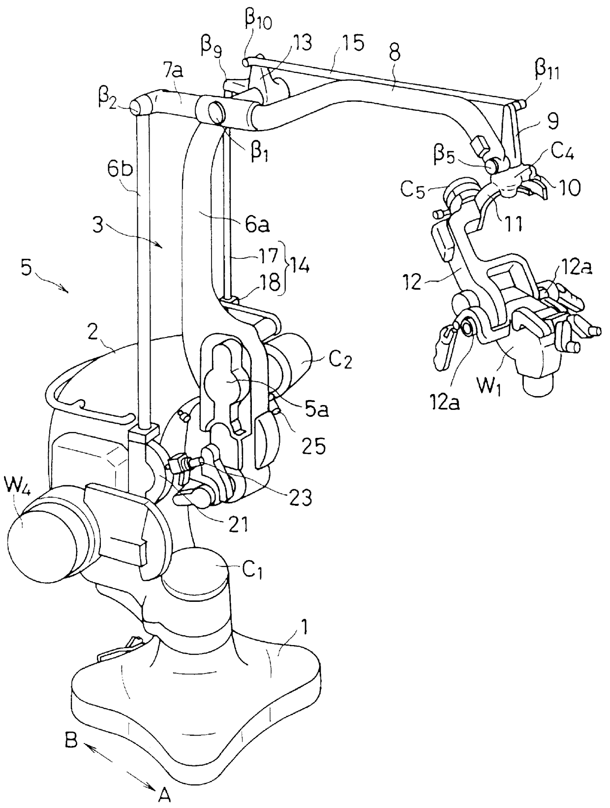
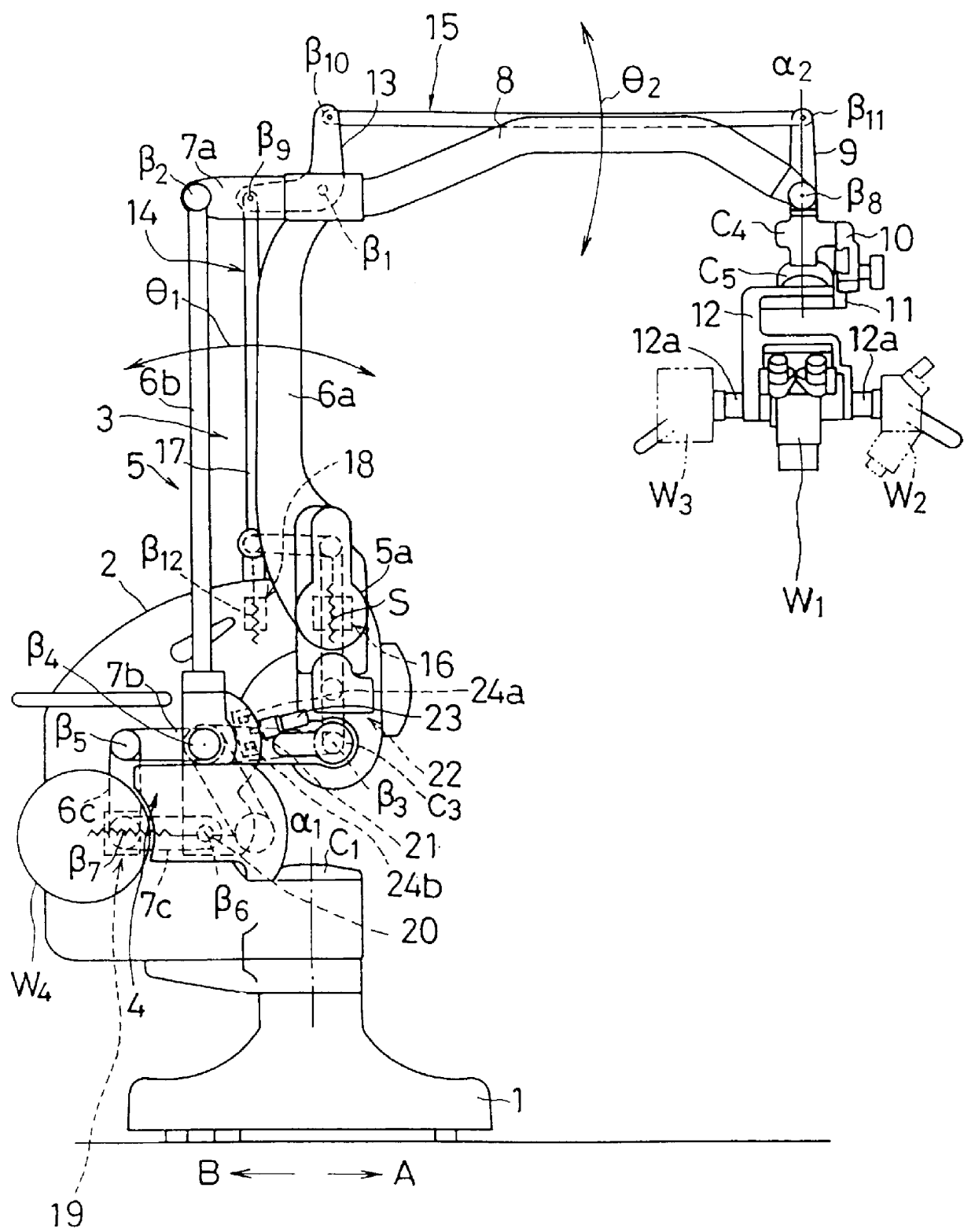
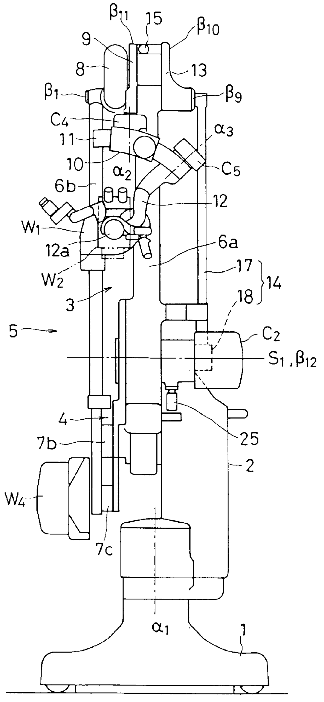
A preferred embodiment of the present invention will be described in more details referring to the accompanying drawings. It should be noted that the front and rear directions are represented by A and B respectively throughout the drawings.

Denoted at 1 a base installed on the floor of an operation room. A swivel mount 2 which rotates about a vertical pivot axis .alpha..sub.1 is mounted on the base 1. The rotation about the pivot axis .alpha..sub.1 can be locked by the action of an electromagnetic clutch C.sub.1. The mount 2 has a horizontal center pivot S supporting a middle part (5a) of a retaining link mechanism 5 which comprises a first parallel link assembly 3 and a second parallel link assembly 4. The retaining link mechanism 5 includes a group of three vertical arms 6a, 6b, and 6c and another group of three horizontal arms 7a, 7b, and 7c. The middle part 5a of the front vertical arm 6a of the retaining link mechanism 5 is pivotally joined to the horizontal center pivot S.

The h...


PUM


Abstract

The vertical movement of a retaining link mechanism and the horizontal movement of a counterweight are interlocked by a drive mechanism for balancing in weight between a medical optical device and / or its auxiliary devices and the counterweight about the center of pivot. Accordingly, the action of the drive mechanism makes a balance in the horizontal and vertical movements of the operating microscope combination, thereby automate the balancing control readily.

Description

1. Field of the InventionThe present invention relates to an automatic balancing mechanism for use with a medical stand apparatus, which is capable of advancing and holding heavy devices such as an operating microscope and its auxiliary devices at a desired spatial position during microsurgery.2. Prior ArtMicrosurgery is known particularly in the fields of brain surgery and cardiac surgery using a operating microscope as a "medical optical device" for viewing and inspecting a part to be treated during the operation. Various stand apparatuses are available for holding at a desired spatial position the heavy devices such as an operating microscope and its auxiliary devices. A typical type of the stand apparatus comprises a retaining link mechanism of parallel link pivotally (or tiltably) mounted at the middle to a support base, an operating microscope mounted to one end of the retaining link mechanism, and a counterweight mounted to the other end of the retaining link mechanism for co...

Claims


Application Information

Patent Timeline
Patent Type & Authority Patents(United States)
IPC IPC(8): A61B19/00F16M11/12F16M11/02G02B7/00G02B21/24
CPCA61B19/26F16M11/08G02B7/001F16M11/18F16M11/2064F16M11/12A61B19/5223A61B2019/265F16M2200/041F16M2200/044A61B50/26A61B50/28A61B90/20A61B90/25A61B90/50A61B2090/506
Inventor NAKAMURA, KATSUSHIGE
Owner MITAKA KOHKI
Why Eureka
Try Eureka