Modular rolling mill

Inactive Publication Date: 2000-04-25
PRIMETALS TECH USA
View PDF4 Cites 33 Cited by
  • Summary
  • Abstract
  • Description
  • Claims
  • Application Information

AI Technical Summary

Problems solved by technology

This too is unsatisfactory because it results in a reduction in the output of the mill.
Lower temperature thermomechanical rolling has also been difficult to achieve, again due to the inability to introduce adequate cooling between the successive rolling units.

Method used


Image

  • Modular rolling mill
  • Modular rolling mill
  • Modular rolling mill

Examples


Embodiment Construction

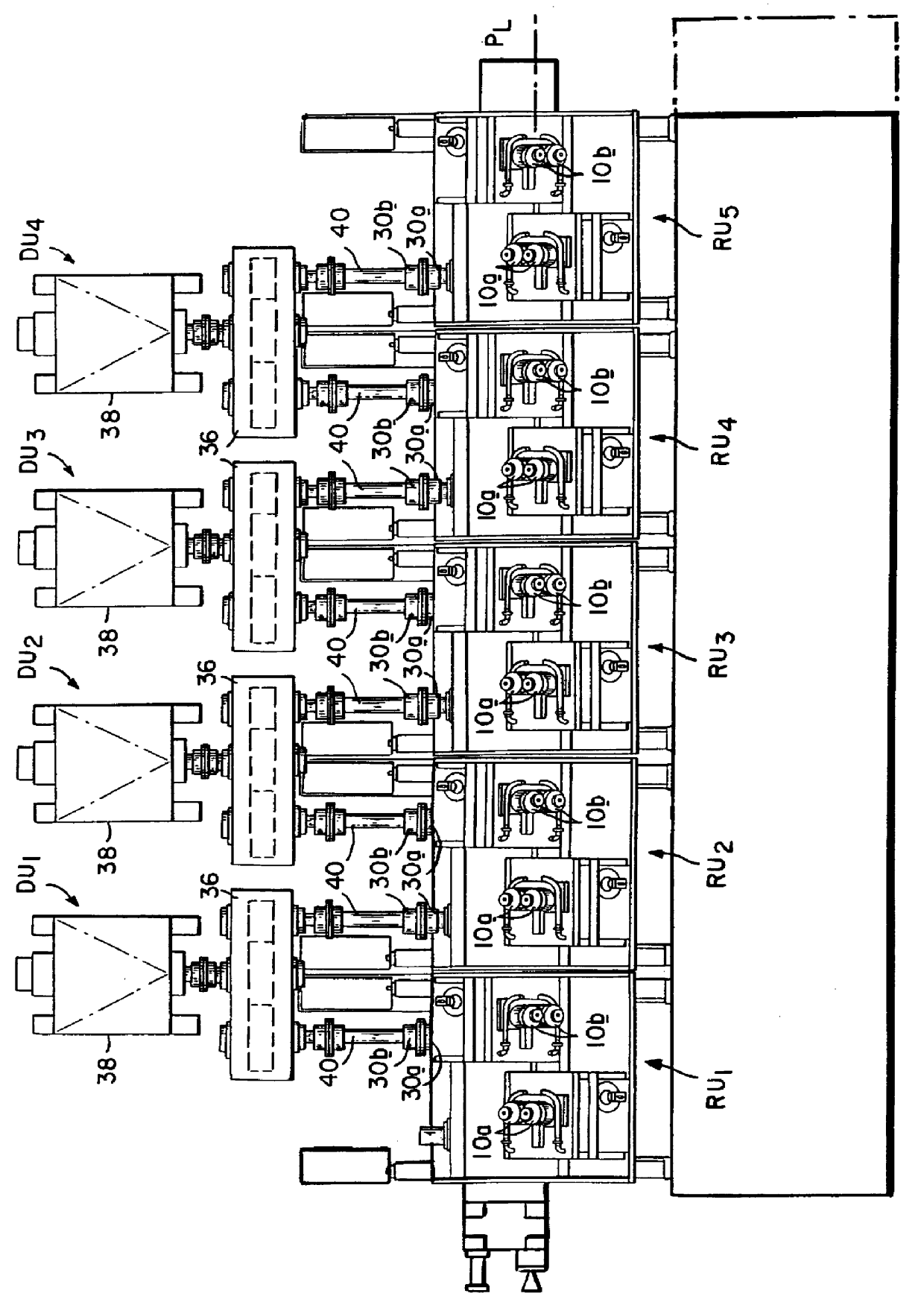
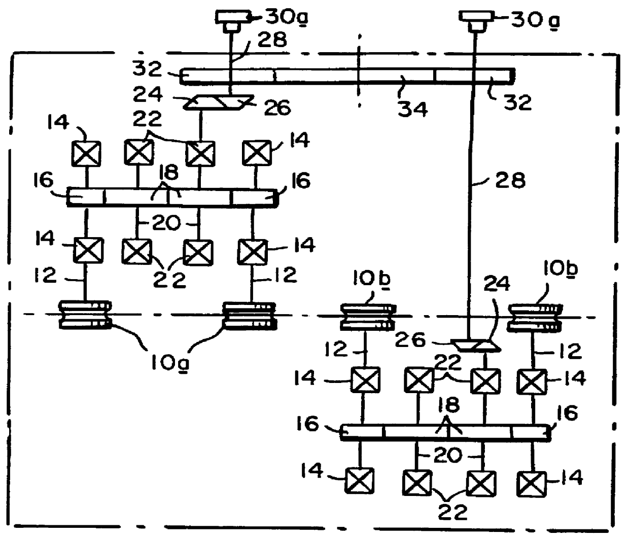
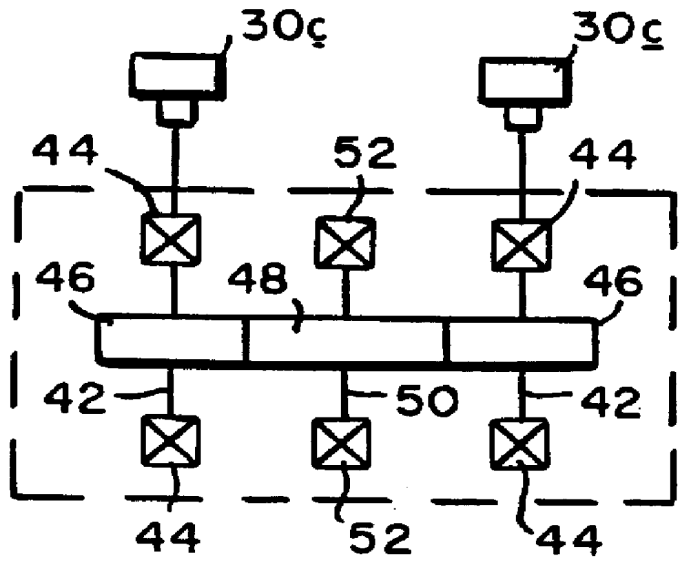
In accordance with the present invention, as shown in FIGS. 4-6, gear units GU.sub.1, GU.sub.2 are installed along the mill pass line P.sub.L in place of dummied rolling units RU.sub.2, RU.sub.4, the latter having been displaced laterally from the mill pass line PL to the "work side" of the mill. As can best be seen in FIG. 5, each gear unit includes input shafts 42 rotatably supported by bearings 44. The input shafts 42 carry gears 46 which mesh with a central gear 48 carried on an intermediate shaft 50 also rotatably supported by bearings 52. The shafts have protruding ends terminating in coupling halves 30c.

The coupling halves 30c are adapted to mate with the coupling halves 30b of the drive units that were previously coupled to the dummied rolling units. The gear trains 46, 48, 46 of the gear units replace the gear trains of the dummied rolling units, thereby accommodating gaps in the rolling sequence without interrupting the overall drive train of the mill.

The gear train of eac...


PUM

PropertyMeasurementUnit
Speedaaaaaaaaaa

Abstract

In a modular rolling mill gear units are installed between selected rolling units in place of other rolling units which haven removed from the mill pass line to thereby provide a gap in the rolling sequence. Each gear unit is coupled to the drive units previously coupled to the respective removed rolling unit, and is configured to provide a continuation of the mill drive train end to accommodate operation of the next subsequent rolling unit at the speed of the respective removed rolling unit. The gear units carry water boxes or other equivalent cooling devices which serve to lower the temperature of the product between successive roll passes.

Description

1. Field of the InventionThis invention relates to single strand modular rolling mills for rolling long products such as bars, rods and the like.2. Description of the Prior ArtWith reference initially to FIG. 1, a known modular rolling mill of the type described in the commonly assigned U.S. Pat. No. 5,595,083 is shown comprising at least three, and in this case, five rolling units RU.sub.1 -RU.sub.5 arranged in succession on a mill pass line P.sub.L. Each rolling unit has multiple pairs of work rolls 10a, 10b. The work rolls may be sized and grooved to provide a typical oval-round pass sequence, with successive roll pairs being offset by 90.degree. to effect a twist-free rolling sequence on a product being directed along the mill pass line.Except for the size and / or groove configuration of the work rolls, the rolling units are identical and interchangeable one for the other at any location along the mill pass line. With reference to FIG. 2, which is a diagrammatic illustration of t...

Claims


Application Information

Patent Timeline
IPC IPC(8): B21B35/00B21B35/12B21B45/02B21B35/02B21B31/00B21B31/08B21B1/16B21B1/18B21B13/00B21B13/12B21B13/14B21B31/07
CPCB21B45/0224B21B35/02B21B35/12B21B1/18B21B13/005B21B31/08B21B13/14
Inventor SHORE, T. MICHAEL
Owner PRIMETALS TECH USA
Why Eureka
Try Eureka