Holder for full or folded collapsible tubes

a technology of collapsible tubes and holder, which is applied in the direction of pliable tubular containers, machine supports, other domestic objects, etc., can solve the problems of difficult to keep the nozzle and cap of the tube clean, affecting the use of the tube, so as to increase the amount of product, simplify the process of basically completely, and facilitate the use

Inactive Publication Date: 2000-05-02
LAYER ROBERT WESLEY
View PDF5 Cites 9 Cited by
  • Summary
  • Abstract
  • Description
  • Claims
  • Application Information

AI Technical Summary

Problems solved by technology

These devices are not claimed to be used to prevent rolled sections of partially emptied tubes from unrolling.
Nor are these devices used to hold a tube while product is being extruded from the tube.
A disadvantage of this holder is that, since the upper inner concave walls of the holder are needed to support the tube, a number of different size holders are needed for different size tubes.
Another disadvantage of this holder is that the upper cylindrical holding portion of the holder hinders access to the tube for extrusion of product.
For example, they are not particularly desirable based on their appearance since they are rather large and must be attached to and protrude from some surface, such as a wall or cabinet.
This is not only wasteful but it also makes it difficult to keep the nozzle and cap of the tube clean.
Many of these devices hold the collapsible tube in an upside-down position and, consequently, suffer from the same disadvantages associated with tubes held in this upside-down position cited above.
The movable section of these devices, which applies pressure to the tube to extrude the product, is difficult to control and promotes the extrusion of excess unwanted product.
Furthermore, these devices are neither simple to manufacture nor to keep clean due to the more intricate nature of their movable section.
However, they are not proposed to be used as holders for a tube.
Because of this, they do little to improve the appearance of a tube, such as a toothpaste tube, that is stored in plain view on sink and counter tops.
Since these devices do not hold a tube, they inconveniently require the use of two hands to extrude product from the tube.
A disadvantage of this fixed-size slot device, which is the same as those for the fixed-size slot devices described in the previous paragraph, is that each device can only be used for tubes having the same wall thickness.
Another disadvantage is that the hollow base, which acts as a receiving chamber for the emptied flattened tube, increases its top-heaviness and decreases its stability.
Thus, this device needs to be undesirably larger and / or heavier to improve its stability compared to a device with a solid base.
Because the von Schuckmann device utilizes flexible squeezing jaws and a fixed-size open slot, it could be difficult to manufacture economically, such as by molding or extruding.
Similarly, both the flexible squeezing jaws and the fixed-size slot are subjected to severe stresses during use which could decrease the service life of the device.
Although this device is simple, it has a number of limitations and drawbacks.
One drawback of this device is that it is proposed to be used with a hook attached to the bottom of the base that holds the clip and tube in an upside-down position.
Furthermore, this device is not designed to hold a tube in the desirable upright position.
Thus, when even a relatively small amount of product is extruded from a tube, the tube will become weak at its narrowest point, which is just above where it is grasped by the gap of the top of the clip, and sag at this point.
A further drawback of this device is that the folded, or rolled, tube must inconveniently be inserted totally into the chamber of the clip from the side.
However, at some point, the tube sags when enough product has been extruded.

Method used


Image

  • Holder for full or folded collapsible tubes
  • Holder for full or folded collapsible tubes
  • Holder for full or folded collapsible tubes

Examples


Embodiment Construction

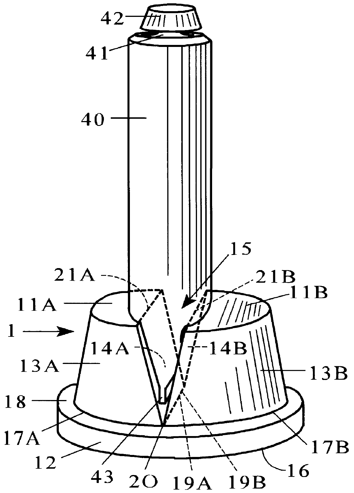
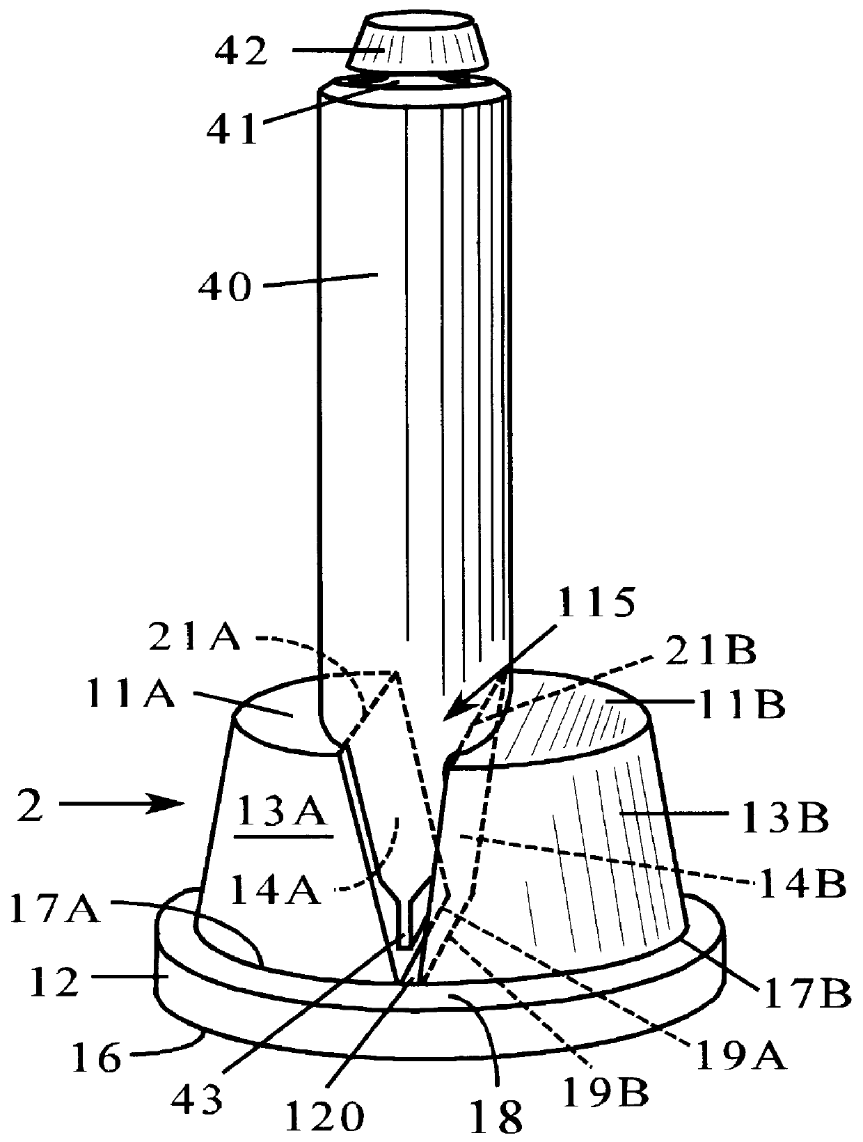
This is an example of a very compact device of this invention that is useful for holding either full or flattened and folded smaller toothpaste tubes containing from say 0.65 oz to about 5 or 6 oz of product, which has the same general shape as holder 1, shown in FIG. 1, and the following specific dimensions. The overall height of the holder is 48 mm. This holder has a supporting cylindrical base with a diameter 65 mm and height of 15 mm. The bottoms of the two side walls of the holder are integrally attached to the top of the base such that their planar inner surfaces face each other and form a V-shaped notch. Including the opening of the V-shaped notch, the side walls form a truncated conical shape whose circular bottom is centered on the top of the base and parallel to its bottom. The diameter of the circular bottom of the truncated conical portion of the holder is 48 mm. Parallel to its bottom, the diameter of the circular top of the truncated portion of the holder is 40 mm. The...


PUM


Abstract

A combination of a compact, economical, decorative, rigid, one-piece holder and a squeezable collapsible dispensing tube, where the holder has a supporting base with a planar bottom standing surface to which are attached two side walls such that their substantially planar inner surface face each other and form a substantially upright V-shaped notch. The dimension of the V-shaped notch, such as its height, its top opening width, and the width of the inner surfaces of the side walls, are such that a sufficient length of the bottom section of a full collapsible dispensing tube fits into and is firmly grasped by the V-shaped notch and is securely held in an upright position. These same dimensions should also be sufficient that a partially-emptied, collapsible dispensing tube, which has been flattened and folded a plurality of time-generally about four or five times for a toothpaste tube-fits into and is securely held upright by the notch of the holder. The firm grasp of the V-notch of the holder on an inserted partially-emptied, flattened, and folded dispensing tube prevents both the tube from unfolding and the product from re-entering the folded section of the tube during use. Because of this, the use of this holder greatly simplfies the process of emptying a product from a tube.

Description

BACKGROUND--FIELD OF INVENTIONThis invention relates to a device for holding a squeezable, flexible, collapsible dispensing tube, which may be anywhere from completely full to substantially empty, that is used for dispensing a variety of products such as toothpaste, cream, ointment, glue, paint, and the like.Many household products, of suitable fluidity, are packaged in squeezable collapsible tubes where the product contained therein is extruded from the tube by manual pressure. However, the use of a collapsible tube has an inherent drawback in that, as more and more of its product is extruded, the tube becomes less full. Now, the product moves both forward toward the nozzle opening at the top of the tube as well as backward to the sealed bottom end of the tube. Consequently, it becomes more and more difficult to extrude the product from the tube. Because of this, the application of manual dispensing pressure on the tube to extrude product becomes less efficient. Typically, to overc...

Claims


Application Information

Patent Timeline
Patent Type & Authority Patents(United States)
IPC IPC(8): B65D35/00B65D35/56
CPCB65D35/56
Inventor LAYER, ROBERT WESLEY
Owner LAYER ROBERT WESLEY
Why Eureka
Try Eureka