Use of multiple masks to control uniformity in coating deposition

Inactive Publication Date: 2000-05-16
NORTHROP GRUMMAN SYST CORP
View PDF5 Cites 61 Cited by
  • Summary
  • Abstract
  • Description
  • Claims
  • Application Information

AI Technical Summary

Problems solved by technology

Surface defects and unevenness can produce a multitude of device infirmities.
Without the necessary high reflectivity, the gyro may be unable to assume operation as a low gain oscillator.
That is, successful gyro operation requires that gyro gain exceed losses for the desired oscillation to occur.
The presence of nonuniform mirr

Method used


Image

  • Use of multiple masks to control uniformity in coating deposition
  • Use of multiple masks to control uniformity in coating deposition
  • Use of multiple masks to control uniformity in coating deposition

Examples


Embodiment Construction

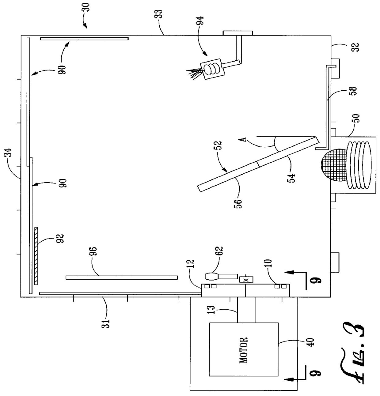
FIG. 3 is a schematic illustration of a vacuum deposition chamber 30 incorporating the present invention. The view of FIG. 3 is taken through the top of the chamber 30. The vacuum deposition chamber has a sealable volume formed by side walls 31, 32, 33, 34. Top and bottom walls (not shown) close off the chamber. The tool 12 holding the substrates to be coated may be mounted along a first side wall 31 of the chamber. As will be understood by those familiar with the art, a portion of the wall 31 holding the tool 12 may be openable to provide access between the chamber and the outside environment. As will also be apparent to those familiar with the art, the chamber 30 may have other shapes, and the elements contained within the chamber may have other orientations.

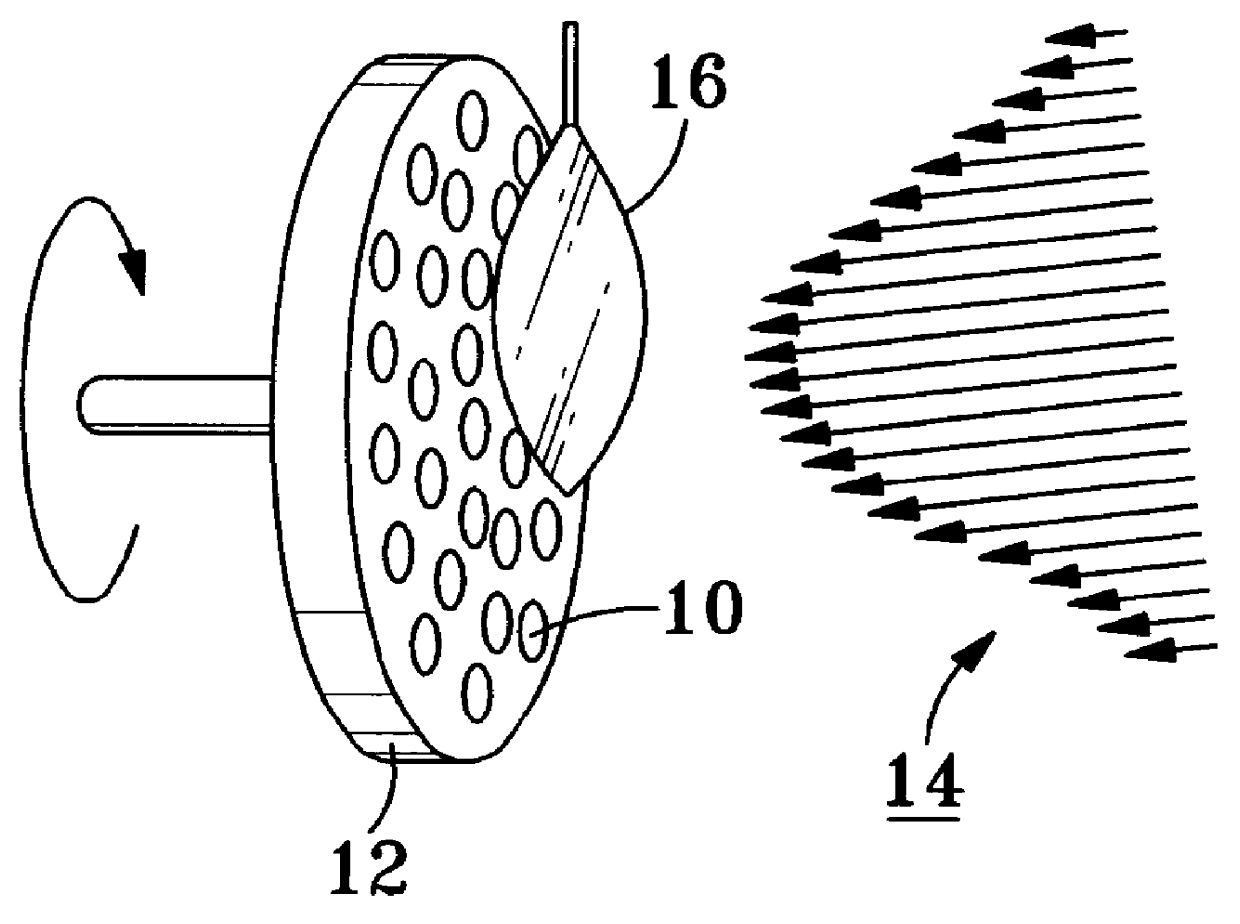
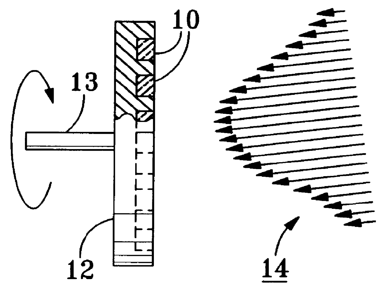
As noted previously, the tool 12 may be mounted on a rotating shaft 13. The shaft may be rotated by a motor 40 attached to the shaft. The motor 40 rotates the shaft 13 at a constant rate during the deposition process. By conti...


PUM

PropertyMeasurementUnit
Thicknessaaaaaaaaaa
Shapeaaaaaaaaaa

Abstract

The uniformity of individual layers of multiple coating materials deposited on a substrate in a vacuum deposition process (such as for manufacturing mirrors for use in ring laser gyroscopes) is improved by an apparatus and method that include changing the masks placed in front of the substrate upon which the coating materials are to be deposited. Separate masks are tuned for each particular coating material to compensate for the unique plume shape of the material, and provide a uniform deposition of that particular coating material. Each mask is positioned in front of the substrate when the material for which the mask has been tuned is being deposited. The masks are changed when the coating material is changed, without venting the chamber.

Description

1. Field of the InventionThe present invention relates to processes for fabricating mirrors suitable for use in precision instruments such as ring laser gyroscopes. The present invention also relates to processes for depositing multiple coatings on a substrate, such as a mirror substrate. More particularly this invention pertains to a process for controlling the thickness of mirror layers deposited upon a mirror substrate within a deposition chamber.2. Description of the Prior ArtA ring laser gyroscope is a rotation sensor that senses rotation about an axis that is perpendicular to the plane of a cavity formed within a frame, preferably of glass ceramic or other low thermal coefficient material. Highly polished mirrors are positioned at the corners of the cavities to direct the counterpropagating beams about the cavity. Beams of laser light circulate in opposite directions within the cavity. In accordance with the well-known Sagnac effect, the frequencies of the two beams are altere...

Claims


Application Information

Patent Timeline
IPC IPC(8): C23C14/46C23C14/04
CPCC23C14/46C23C14/044
Inventor PAVELL, JAMES M.LEE, CHONG C.CHERBETTCHIAN, AGOP H.STEWART, ALAN F.
Owner NORTHROP GRUMMAN SYST CORP
Why Eureka
Try Eureka