
Dither motor having integrated drive and pickoff transducers

a technology of pick-off transducer and drive spring, which is applied in the direction of speed measurement using gyroscopic effects, instruments, surveying and navigation, etc., can solve the problems of adding stiffness to the dither spring and costing the ring laser gyroscope produ

Inactive Publication Date: 2008-05-20
HONEYWELL INT INC
View PDF9 Cites 2 Cited by
  • Summary
  • Abstract
  • Description
  • Claims
  • Application Information

AI Technical Summary

Benefits of technology

This configuration enhances the dither motor's flexibility, reduces weight and cost, and improves signal consistency, effectively preventing lock-in conditions in ring laser gyroscopes at low rotational rates.

Problems solved by technology

The separate pickoff and drive piezoelectric transducers add stiffness to the dither spring and cost to the ring laser gyroscope product.

Method used


Image

  • Dither motor having integrated drive and pickoff transducers
  • Dither motor having integrated drive and pickoff transducers
  • Dither motor having integrated drive and pickoff transducers

Examples


Embodiment Construction

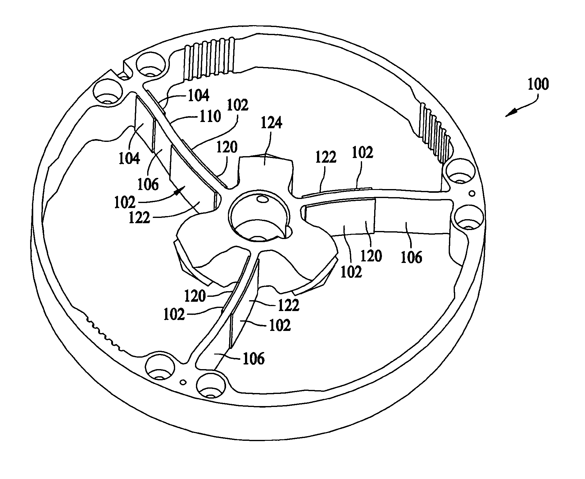
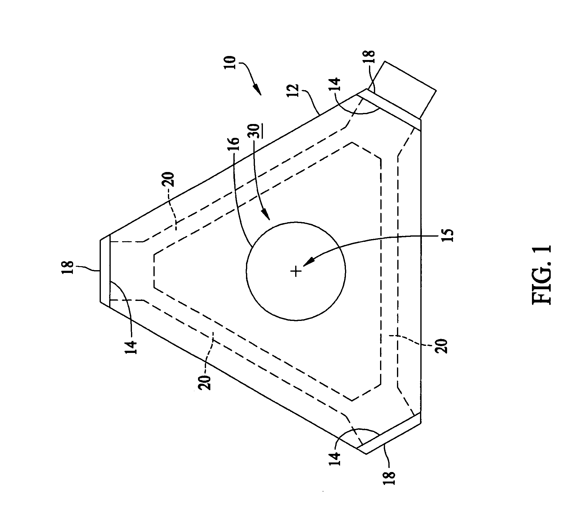
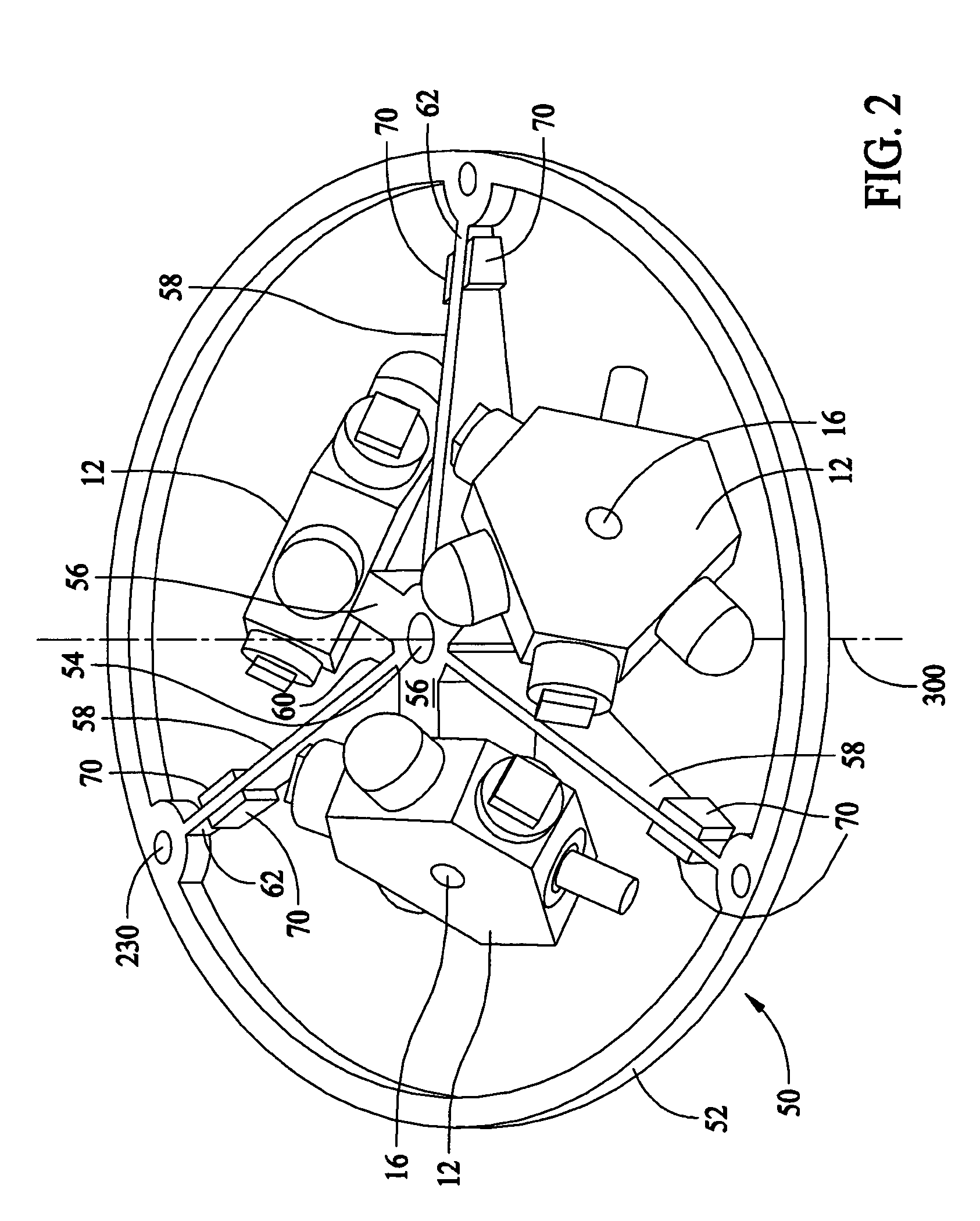
[0016]FIG. 1 is a top plane view of a ring laser gyroscope, generally indicated by the numeral 10, that includes a laser block 12 which provides a closed-loop optical path having three or more apexes 14. A cylindrical mounting bore 16 is located centrally in the block 12, for example, about an axis 15 at the inertial center of gyroscope 10. A plurality of apertures 20 between each apex 14 surround the bore 16 and provide an optical lasing path. Each apex 14 has an appropriate inward facing mirror 18 which in combination provides an optical closed-loop path for counter-propagating laser beams. Although gyroscope 10 is illustrated with a triangular closed-loop path, gyroscope 10 many alternatively be configured with other polygon structures and a corresponding closed loop path.

[0017]Bore 16 configures laser block 12 for mounting on a dithering motor or apparatus as further described below. The dither motor provides an oscillation to laser block 12 for prevention of lock-in. The oscill...


PUM


Abstract

A ring laser gyroscope is described that includes at least one laser gyroscope block and a dither motor, where the gyroscope blocks are configured to engage the dither motor. The dither motor has an outer ring, a hub section, at least one radially extending reed extending between the outer ring and the hub section, and at least one piezoelectric transducer attached the reed. The piezoelectric transducer includes a common piezo-ceramic having a contiguous void line that allows for a separate electrical connection to be made to electrode surfaces on each side of the void line.

Description

BACKGROUND OF THE INVENTION[0001]This invention relates generally to dither motors, for example, dither motors incorporated within ring laser gyroscopes.[0002]In a ring laser gyroscope, two electromagnetic waves in the form of monochromatic light beams are produced which are propagating in opposite directions. A rotation of the ring laser gyroscope about its input axis increases the path length for one light beam whereas the path length for the other light beam is reduced. The resulting path length change produces a frequency shift within each of the light beams since the oscillating frequency of the laser beams depends on the length of the laser path. Therefore the frequency difference is a function of the rotation rate.[0003]At low rotational rates the frequency difference between both light beams becomes small and both light beams have the tendency to oscillate on the same frequency which is sometimes referred to as lock-in. In order to prevent this mutual interference of both li...

Claims


Application Information

Patent Timeline
Patent Type & Authority Patents(United States)
IPC IPC(8): G01C19/70
CPCG01C19/70
Inventor SCHOBER, CHRISTINA M.
Owner HONEYWELL INT INC
Learn More