Therapeutic cold and heat pack system

a gel pack and cold technology, applied in the field of medical therapy devices, can solve the problems of constant variation of pain becoming painfully uncomfortable, and increasing the intensity of the tightness

Inactive Publication Date: 2000-07-25
DIKEN KATHRYN E +1
View PDF7 Cites 46 Cited by
  • Summary
  • Abstract
  • Description
  • Claims
  • Application Information

AI Technical Summary

Problems solved by technology

More particularly, in order to effectively secure a therapeutic pad in any type of secure and useful position on a person's body, conventional hook and loop fastener type straps must be tightened to such a degree as to become painfully uncomfortable.
The pain is even more pronounced when these straps are positioned around muscles and other parts of the person's body which normally contract and expand, thereby continually varying the intensity of the tightness.

Method used


Image

  • Therapeutic cold and heat pack system
  • Therapeutic cold and heat pack system
  • Therapeutic cold and heat pack system

Examples


Embodiment Construction

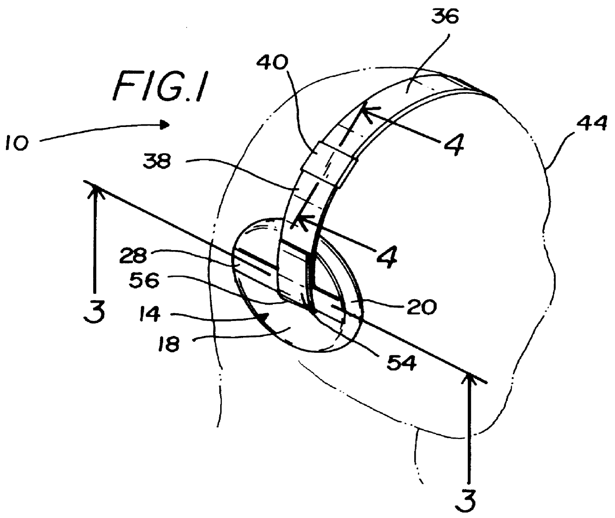
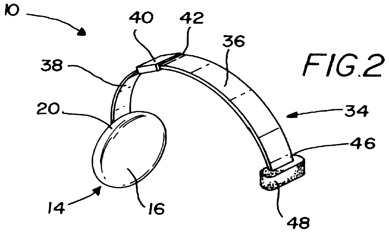
In FIG. 1, first gel pad assembly 10 includes first pad 14 having a generally planar, circular configuration and inner face 16, outer face 18, rounded peripheral edge 20. Cross section 3--3 of FIG. 1 is illustrated in FIG. 3. Referring to FIG. 3, first pad 14 comprises cover 22 which encapsulates first pad 14, and lining 24 attached to cover 22. In the preferred embodiment cover 22 is made of cloth and lining 24 is made of plastic. Gel 26 is adapted to be selectively heated and cooled by conventional means, and is sealed within lining 24. As used herein the term gel means a semi-rigid colloidal dispersion of a solid within a liquid which retains heat or cold depending on the temperature to which the gel has been subjected. Short strip 28 has short strip first end 25 fixedly engaged to outer face 18 and short strip second end 27 fixedly engaged to outer face 18, and short strip 28 extends across outer face 18. Short strip 28, when affixed to outer face 18, defines opening 30 between ...


PUM


Abstract

A gel pad and gel pad system for application of heat or cold to various parts of a human body through the use of a pad and headpiece, pad and strap or a combination of pad, headpiece, pad and strap.

Description

1. Field of the InventionThe present invention relates to medical therapy devices and more particularly to a system of heated or chilled gel packs for positioning against different parts of a human body.2. Description of the Prior ArtThe use of medical therapy devices that employ the use of chilled or heated gel packs, along with their attendant attachment structures, is known in the prior art. For example, U.S. Pat. No. 5,393,462, issued to Avery on Feb. 28, 1995, discloses a refrigerant gel pad for heating or cooling portions of a person's body. The '462 patent is silent on how the gel pad would be attached to the body.A typical attachment structure for use with a refrigerant gel pack is shown in U.S. Pat. No. 5,409,500, issued to Dyrek on Apr. 25, 1995. In the '500 patent, a therapeutic cold pack filled with a refrigerant gel, is attached to the body by straps having hook and loop fasteners. Similarly, U.S. Pat. No. Des. 383,547, issued to Mason et al. on Sep. 9, 1997, discloses ...

Claims


Application Information

Patent Timeline
Patent Type & Authority Patents(United States)
IPC IPC(8): A61F7/00A61F7/02
CPCA61F7/02A61F2007/0005A61F2007/0231
Inventor DYKEN, KATHRYN E.DYKEN, JACK A.
Owner DIKEN KATHRYN E
Why Eureka
Try Eureka