Process controlled carrier dispensing

Inactive Publication Date: 2000-07-25
XEROX CORP
View PDF4 Cites 12 Cited by
  • Summary
  • Abstract
  • Description
  • Claims
  • Application Information

AI Technical Summary

Problems solved by technology

As the developer material ages its critical properties change, and when the material approaches the end of its useful life, copy quality deteriorates.
Thus, the fixed toner to carrier ratio approach does not necessarily provide the optimal rate of material replenishment, nor can it optimally compensate for the developer material aging rate changes due to variable factors such as area coverage, humidity, and / or temperature.
The above problem is more acute in a color system employing several developer units where small variations in the developability of an individual color become readily apparent as significant hue shifts in the final out output.

Method used


Image

  • Process controlled carrier dispensing
  • Process controlled carrier dispensing
  • Process controlled carrier dispensing

Examples


Embodiment Construction

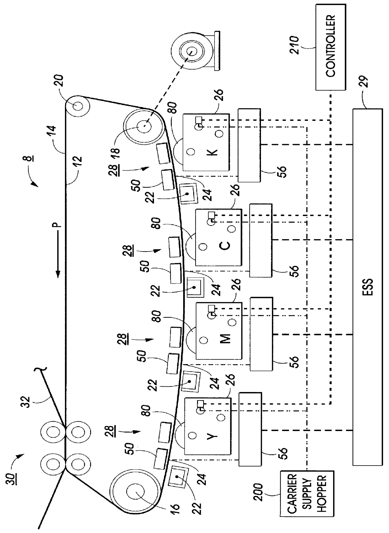
Referring to FIG. 1 of the drawings, there is shown a xerographic type reproduction machine 8 incorporating an embodiment of the non-interactive agitated magnetic brush of the present invention, designated generally by the numeral 80. Machine 8 has a suitable frame (not shown) on which the machine xerographic components are operatively supported. As will be familiar to those skilled in the art, the machine xerographic components include a recording member, shown here in the form of a rotatable photoreceptor 12. In the exemplary arrangement shown, photoreceptor 12 comprises a belt having a photoconductive surface 14. The belt is driven by means of a motorized linkage along a path defined by rollers 16, 18 and 20, and those of transfer assembly 30, the direction of movement being counter-clockwise as viewed in FIG. 1 and indicated by the arrow marked P. Operatively disposed about the periphery of photoreceptor 12 are charge corotrons 22 for placing a uniform charge on the photoconduct...


PUM


Abstract

An electrophotographic printing machine in which an electrostatic latent image recorded on an imaging surface is developed with toner particles to form a visible image thereof, including a hopper containing a supply of carrier material; a first developer unit for developing the electrostatic latent image with toner particles of a first color; a second developer unit for developing the electrostatic latent image with toner particles of a second color; conduit for connecting the first and second developer unit to the hopper so that carrier material flows to the first and second developer unit; a first feeding system, in communication with the conduit, for regulating the amount of carrier to the first developer unit; a second feeding system in communication with the conduit, for regulating the amount of carrier to the second developer unit, and a controller for controlling the regulation rate of the first and the second feeding system independently.

Description

BACKGROUND OF THE PRESENT INVENTIONThe invention relates generally to an electrophotographic printing machine and, more particularly, to a process control system for carrier dispensing in a color electrophotographic printing machine.Generally, an electrophotographic printing machine includes a photoconductive member which is charged to a substantially uniform potential to sensitize the surface thereof. The charged portion of the photoconductive member is exposed to an optical light pattern representing the document being produced. This records an electrostatic latent image on the photoconductive member corresponding to the informational areas contained within the document. After the electrostatic latent image is formed on the photoconductive member, the image is developed by bringing a developer material into proximal contact therewith.Typically, the developer material comprises toner particles adhering triboelectrically to magnetic carrier granules. This two component mixture is br...

Claims


Application Information

Patent Timeline
IPC IPC(8): G03G15/01
CPCG03G15/0126G03G2215/017
Inventor HART, STEVEN C.
Owner XEROX CORP
Why Eureka
Try Eureka