Custom-fabricated golf club device and method

a golf club and golf club technology, applied in golf clubs, racket sports, golf accessories, etc., can solve the problems of limited adjustment, difficult modification of the lie of the golf club, and especially of the iron club, and achieve the effect of wide range of lie angles, precise resolution, and enhanced golfing level of play

Inactive Publication Date: 2000-09-19
DRAKE STANLEY
View PDF15 Cites 108 Cited by
  • Summary
  • Abstract
  • Description
  • Claims
  • Application Information

AI Technical Summary

Benefits of technology

In contrast, the present invention utilizes a hosel to blade type weldment and locating groove, with the result that a wide range of lie angles with precise resolution can be achieved.
As such, it is an object of the present invention to provide a club that best suits the individual golfer, taking into account all relevant physical characteristics of said individual, including, but not limited to the height of the user, the strength of the user, and the preferred stance of the user.
It is a further object of the present invention to provide a club that enhances the level of play of the golfer, supplying the best club available

Problems solved by technology

Although the Chang device uses a locating groove, such is designed for usage with the conventional metal wood configuration, and can not apply to irons.
Additionally, the flat planar surfaces limit the degree of adjustment by mating with the end walls of the slot when maximum clockwise and counterclockw

Method used


Image

  • Custom-fabricated golf club device and method
  • Custom-fabricated golf club device and method
  • Custom-fabricated golf club device and method

Examples


Embodiment Construction

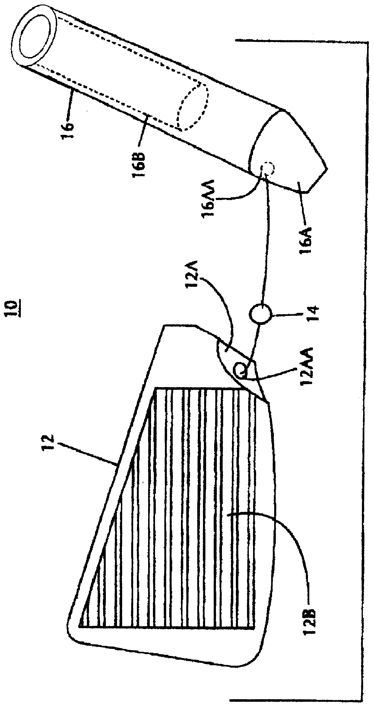
FIG. 1 is an exploded view of the hosel assembly, steel ball, and club head of the present invention, wherein the hosel assembly is rotated in a counter-clockwise manner and the upper portion of the hosel assembly leans away from the viewer.

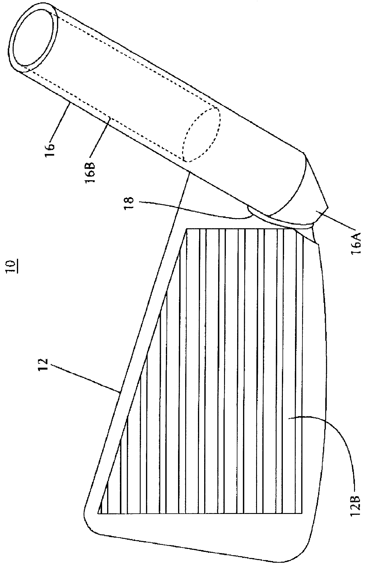
FIG. 2 is a front perspective view of the custom-fabricated golf club device of the present invention.

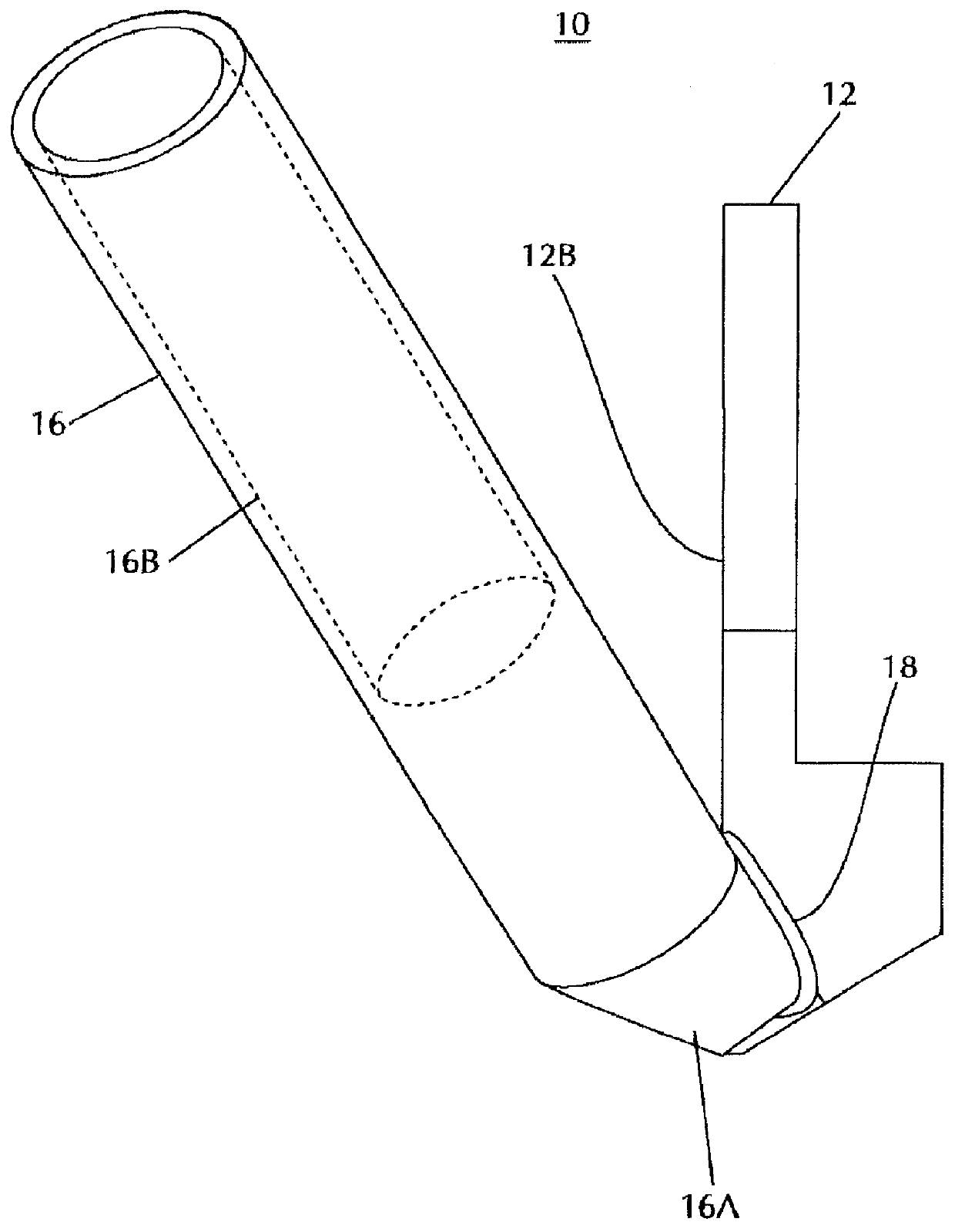
FIG. 3 is a side perspective view of the custom-fabricated golf club device of the present invention.

The foregoing will describe the principal components of the present invention as distinguished from the prior art. Typically, a golf club head of an iron consists of the blade portion and the hosel, or neck piece. Although the prior art devices regarded such as inseparable, the present invention aims to manufacture the hosel and the blade separately and then join them in such a manner as to more adequately suit the individual user.

Firstly, referring to FIG. 1, which is an exploded view of the hosel assembly, steel ball, and club head of the presen...


PUM


Abstract

A custom-fabricated golf club device comprising a golf club head with a recessed portion located at the front heel portion of the head and machined therein, the recessed portion comprising a substantially semi-spherical aperture. A hosel assembly has a lower portion, having a substantially semi-spherical aperture that aligns with the aperture of the head recessed portion, the hosel assembly further having a recessed portion at an upper portion thereof. A steel ball is located securely within the aperture of head recessed portion and the aperture of the hosel assembly lower portion, functioning to provide positive location of the club head and hosel assembly. In the preferred mode, a permanent weldment functions to securely affix the lower portion of the hosel assembly to the club head at the heel portion of the club head. The device is utilized in conjunction with golf clubs of both the iron and wedge variety to provide a cost-effective and convenient way to custom-fabricate golf clubs to the unique physical characteristics of individual players. By taking advantage of machining, rather than forging or casting the components, a wide range of lie angles with precise resolution can be achieved. In addition, the manufacturing techniques of the present invention diligently conform to the USGA rule that clubs other than putters shall not be designed to be adjustable except for weight.

Description

1. Field of the InventionThe present invention is a custom-fabricated golf club device and method. More particularly, it is an improved means to custom-fabricate golf clubs and irons to individual users in a cost effective manner, taking advantage of machining, rather than forging or casting the components. Specifically, the present invention is a means to better incorporate a golf club's "lie"--the angle that the shaft of the club, resting on the ground, makes with the horizontal. By utilizing a unique hosel to blade type weldment, and, in the preferred mode, machining a locating groove in the blade to which the hosel is joined, a wide range of lie angles with precise resolution can be achieved, where previous configurations provided for minimal adjustment. Moreover, the manufacturing techniques of the present invention diligently conform to USGA Rule 4-1a, relating to the design of clubs, which states that "Clubs other than putters shall not be designed to be adjustable except for...

Claims


Application Information

Patent Timeline
IPC IPC(8): A63B53/02
CPCA63B53/02A63B2053/025A63B53/025A63B60/00
Inventor DRAKE, STANLEY
Owner DRAKE STANLEY
Why Eureka
Try Eureka