Foundation footing construction method, particularly as serve to efficiently precisely emplace wall anchors

a construction method and foundation technology, applied in foundation engineering, manufacturing tools, forms/shuttering/falseworks, etc., can solve the problems of little resistance to uplift of the warping rod support and the ability to effectively thread into the earth

Inactive Publication Date: 2000-09-19
BUTLER MICHAEL G
View PDF9 Cites 45 Cited by
  • Summary
  • Abstract
  • Description
  • Claims
  • Application Information

AI Technical Summary

Problems solved by technology

The Waring rod supports offer little resistance to uplift because they are of normal machine thread...

Method used


Image

  • Foundation footing construction method, particularly as serve to efficiently precisely emplace wall anchors
  • Foundation footing construction method, particularly as serve to efficiently precisely emplace wall anchors
  • Foundation footing construction method, particularly as serve to efficiently precisely emplace wall anchors

Examples


Embodiment Construction

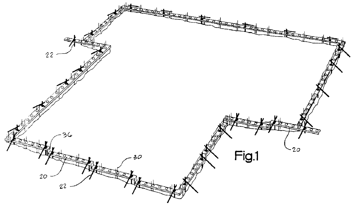
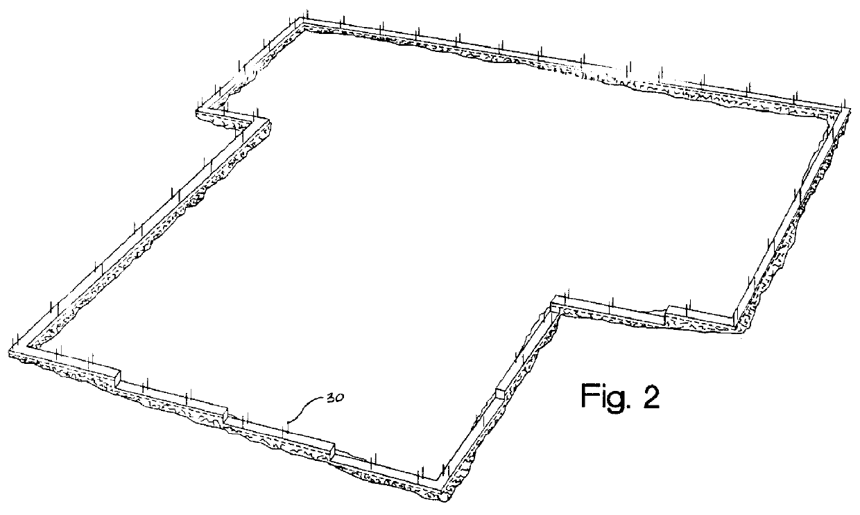
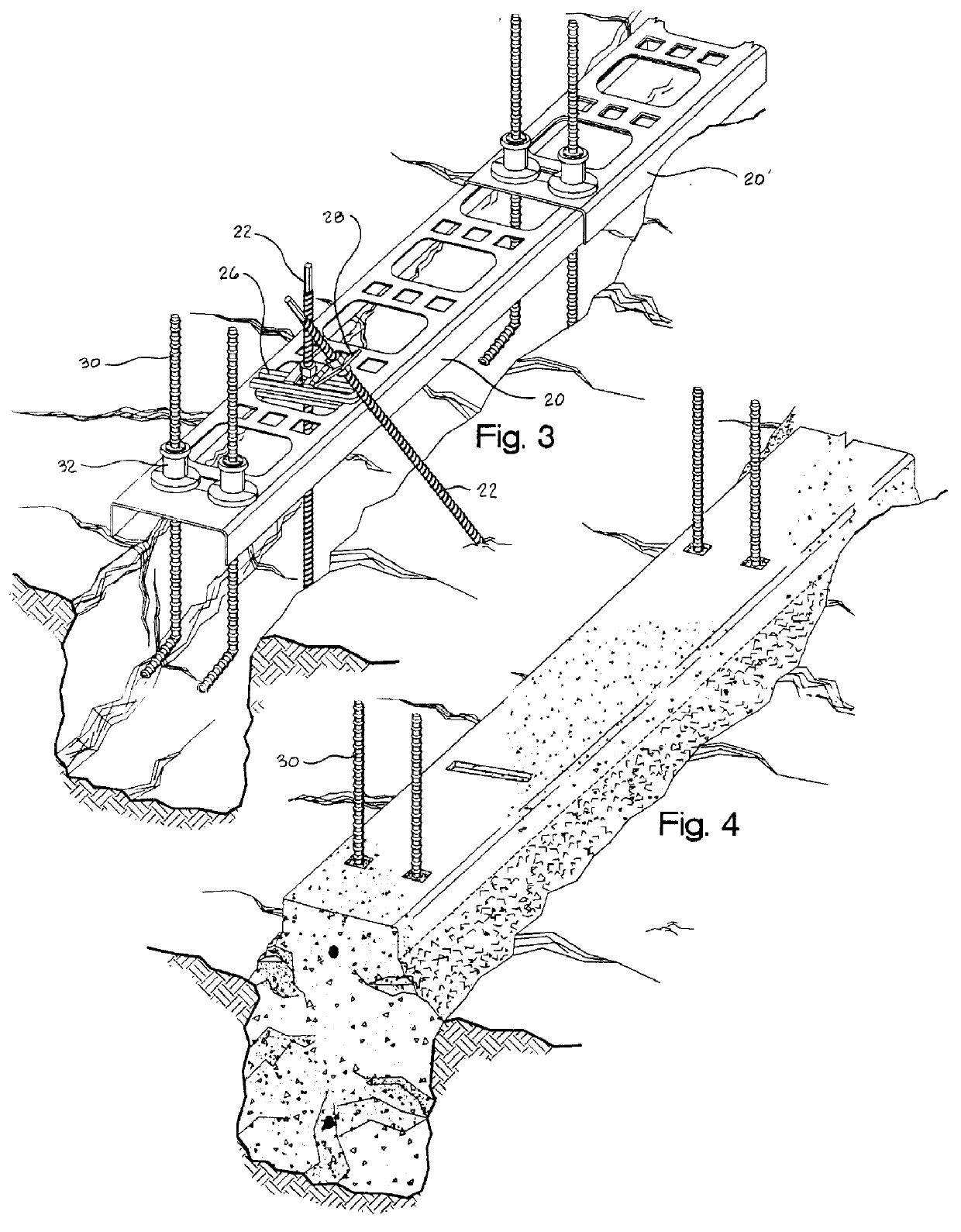
Beginning in the drawings FIG. 1, a perimeter to a building foundation on a sloping site has been trenched for placement of in-situ concrete footings which will support subsequent foundation walls. The starting point of these walls, linear horizontal segments, has been defined by lengths of a guide track 20. Each length of guide track 20 is supported in place by sets of a threaded stake 22, in conjunction with other hardware described below. Track 20 in turn supports vertical lengths of a reinforcing bar 30 which are typically required to bond any subsequent foundation wall which is of a cast in-situ structure.

To both accommodate the site slopes and ideally the modular increments of a particular foundation wall construction, lengths of guide track are stepped vertically to create ordered straight level segments for subsequent wall construction, and are physically connected at those steps by an element described below. Since this method is primarily the starting point for subsequent ...


PUM

PropertyMeasurementUnit
Lengthaaaaaaaaaa
Pressureaaaaaaaaaa
Angleaaaaaaaaaa

Abstract

A concrete footing for the construction of a wall is created by the placement of a guide member with a series of very large holes, which is supported with adjustable threaded stake supports. This guide is situated along a location which will become the top surface of that footing, typically within the confines of a footing trench. Concrete is conventionally placed via a pump through the large holes thus filling the trench void up to the guide element underside. Adjacent guides are attached with plastic connectors which also fixture vertical reinforcing elements which disassemble to strip guides, typically immediately after concrete has been placed.

Description

1. Field of the InventionThe present invention generally concerns methods and devices for the construction upon the surface of the earth of cast in-situ concrete footings which footings serve as support for subsequently built foundation walls, and the like.The present invention particularly concerns fixtures that efficiently define the top surfaces and the edges of cast in-situ concrete footings, and that accurately locate cast-in-place elements which cooperate structurally with subsequently superimposed walls, which walls can be constructed from any of solid concrete, grouted building blocks of cement-masonry or foam units, shot-creted insulated panels, et cetera.2. Description of Prior Art2.1 General BackgroundTraditionally built footings for cement masonry unit (CMU) foundation walls are made of cast in-situ concrete, often having a top surface defined only by string lines and manual tooling (except in the case of basement construction, where the footing is traditionally formed w...

Claims


Application Information

Patent Timeline
IPC IPC(8): E04G13/00E02D27/00E02D27/02E04B5/10E04B5/14
CPCE02D27/00E02D27/02E04B5/10E04G13/00E02D2220/00
Inventor BUTLER, MICHAEL G.
Owner BUTLER MICHAEL G
Why Eureka
Try Eureka