Slide rail for vehicle seat and seat comprising such a slide rail

a vehicle seat and slide rail technology, which is applied in the direction of moving seats, machine supports, other domestic objects, etc., can solve the problems of unintentional activation and the possibility of very serious consequences for the seat passenger, and accidental unlocking of the slide rail

Inactive Publication Date: 2000-10-03
BERTRAND FAURE EQUIP SA (FR)
View PDF7 Cites 32 Cited by
  • Summary
  • Abstract
  • Description
  • Claims
  • Application Information

AI Technical Summary

Benefits of technology

By means of these arrangements, the slide rail unlocking control involves only a horizontal movement of the slider in the transverse direction, which prevents any interference with the slide rail environment in the event of the vehicle being involved in an accident.
the operating mechanism additionally comprises a first non horizontal guide path which is fixed to the slider and along which the activating component slides, the first guide path being configured so that the activating component is in its up position when the slider is in its neutral position, and so that said activating component is in its down position when the slider is in is active position thus, the force that the seat passenger has to exert in order to activate the slide rail catch may be easily controlled throughout the travel of said catch at the design stage of the slide rail, through an appropriate choice of shape of the first guide path;

Problems solved by technology

Because this pivoting component may be accessed outside the slide rail, it may possibly be activated unintentionally, for example if the vehicle is involved in an accident (impact from unsecured luggage or some other object, crushing of the seat passenger into the seat part from the impact caused by the accident, etc.).
In this case, the accidental unlocking of the slide rail may have very serious consequences for the seat passenger.

Method used


Image

  • Slide rail for vehicle seat and seat comprising such a slide rail
  • Slide rail for vehicle seat and seat comprising such a slide rail
  • Slide rail for vehicle seat and seat comprising such a slide rail

Examples


Embodiment Construction

In the different figures the same references denote identical or similar components.

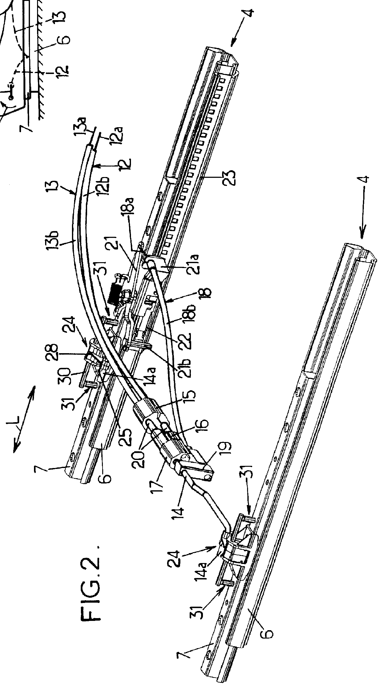
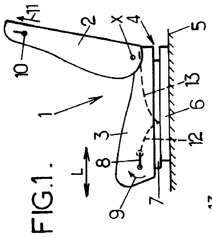
FIG. 1 shows a vehicle seat 1, particularly an automobile vehicle front seat, which comprises a back part 2 pivoting mounted on a seat part 3, around a transverse horizontal axis X, the seat part being itself supported by two parallel slide rails 4 fixed to the floor 5 of the vehicle.

Each slide rail 4 comprises, on the one hand, a fixed section 6 which is fixed to the floor 5 of the vehicle, and on the other hand, a mobile section 7 which is fixed to the seat part of the seat and which is sliding mounted along the fixed section in a longitudinal direction L.

Each slide rail 4 is normally locked in position, as will be explained below, and the two slide rails may be simultaneously unlocked by the activation of a handle 8 in the direction of the arrow 9, so as to allow the longitudinal position of the seat 1 to be adjusted.

Moreover, in the example considered, the seat 1 additionally comprises a handle 1...


PUM


Abstract

This concerns a slide rail for a vehicle seat, comprising a fixed section, a mobile section sliding on the section, and a catch movable vertically between a locked position and an unlocked position allowing the mobile section to slide. The catch is controlled by a rigid rod in the shape of a crankshaft which pivots on the mobile section and which slides in an inclined groove integral with a slider which is movable transversally on the mobile section.

Description

The present invention relates to slide rails for vehicle seats and to seats comprising such slide rails.More particularly, the invention concerns a slide rail for a vehicle seat, comprising:a fixed section, which extends in a so-called longitudinal direction and which is intended to be fixed to the floor of the vehicle,a mobile section, which is intended to be fixed to the seat part of the seat and which is sliding mounted along the fixed section in said longitudinal direction,at least one catch which is mounted on the mobile section and which is movable between, on the one hand, a locked position wherein said catch engages with the fixed section to lock the mobile section, and on the other hand, an unlocked position wherein said catch does not engage with the fixed section and allows the mobile section to slide, the slide rail catch being pulled resiliently to its locked position, and said catch comprising at least one activating part which is movable approximately vertically when ...

Claims


Application Information

Patent Timeline
Patent Type & Authority Patents(United States)
IPC IPC(8): B60N2/08B60N2/06B60N2/07
CPCB60N2/0705B60N2/0875B60N2/0818B60N2/0715
Inventor TIMON, MICHELCASELLAS, PIERRE MORADELL
Owner BERTRAND FAURE EQUIP SA (FR)
Why Eureka
Try Eureka