Simple lift assist module

Inactive Publication Date: 2000-11-14
APPLIED MATERIALS INC
View PDF9 Cites 21 Cited by
  • Summary
  • Abstract
  • Description
  • Claims
  • Application Information

AI Technical Summary

Benefits of technology

The shortcoming and difficulties of the prior art are reduced or solved by use of a configuration according to the present invention. A configuration according to the invention includes a hinged weight support apparatus having: a tubular pan body fixed to a base; a load arm rotatably fixed to an upper tilt axis of the pan body; where a weight support portion of the load arm extends in a first direction from the upper tilt axis; where a crank arm portion of the load arm exte

Problems solved by technology

The lifting of heavy pieces of industrial equipment is a well known and never-ending problem, well known to those who have worked in large industrial plants.
As the size of the equipment increases the weight of components which occasionally need to be removed for servicing also increases.
However, unlike the common industrial plant where floor space is usually readily available or designed to accommodate particular serviceability and maintenance requirements, and where the shop environment is controlled at most by enclosing the machine in a building that has doors which can be closed, the semiconductor processing industry has for the most part already constructed and invested heavily in substrate processing facilities where the dis

Method used


Image

  • Simple lift assist module
  • Simple lift assist module
  • Simple lift assist module

Examples


Embodiment Construction

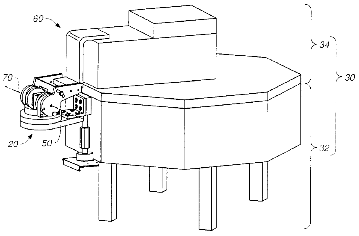
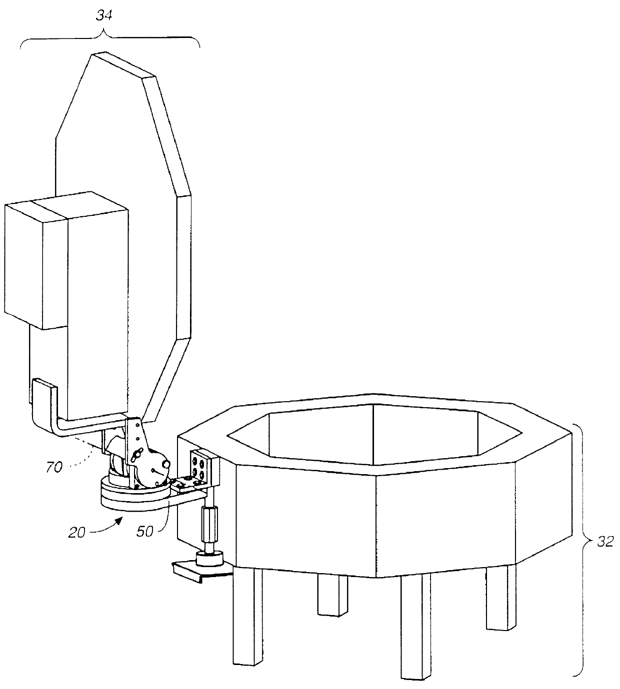
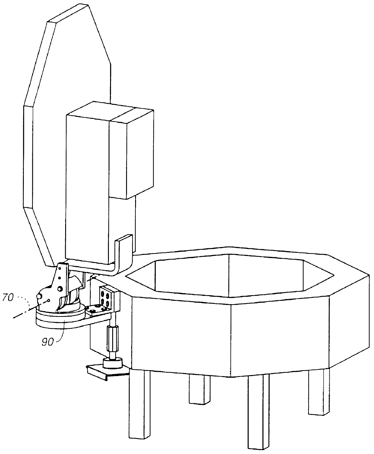
A lifting device assembly 20 according to the invention is shown attached to a process chamber assembly 30 in FIG. 1A. A base 50 of the lifting device assembly 20 is fixed to a lower body portion 32 of the process chamber assembly 30. A load arm assembly 60 of the lifting device assembly 20 is fixed to a lid assembly (top, upper portion) 34 of the process chamber assembly 30. In FIG. 1A the lid assembly 34 is shown in what is considered a closed position. In this configuration, the lifting device assembly 20 causes the load arm assembly 60 to exert an force on the lid assembly 34, urging the lid assembly 34 upwards to rotate around a load arm pivot axis 70 of the lifting device assembly. The force urging the lid assembly 34 upwards is less than the force due to the weight of the lid assembly urging the lid assembly downwards to a closed position, so that the lid remains closed and moves to a closed position if allowed to rotate freely.

FIG. 1B shows the lifting device assembly 20 and...


PUM


Abstract

A compact lifting device whose load arm is fixed to a cover of lid of a processing chamber provides, a tubular pan body with an externally easily adjustable spring counterweight type member passing through the tubular center of the pan body. The spring member is cleverly mounted between an upper and lower portion of the pan body and rotates with the pan body as the lift mechanism swings from side to side. An innovative center core mounting of the spring device allows loads from the lifted weight to be equally distributed on two side of the pan body. The rotation of the pan body is by the use of bearings which are constructed so that a flange of pan body is utilized as two races of a ball bearing further reducing the space need for mounting such a lifting device.

Description

FIELD OF THE INVENTIONThis invention relates to devices which assist in lifting loads, in general, and in particular to lift devices which assist in reducing the weight of a moveable portion of a machine by using a spring force to counterbalance the weight of moveable portion of the machine, where the moveable portion of the machine is the cover or upper portion of a processing vessel.BACKGROUND OF THE INVENTIONThe lifting of heavy pieces of industrial equipment is a well known and never-ending problem, well known to those who have worked in large industrial plants. Over the years various devices have been developed to assist operators and maintenance workers in lifting chores and prevent back and other muscular-skeletal injuries. These prior art devices include overhead cranes, jib cranes, portable cranes, various kinds of floor jacks, and counterweighted and spring loaded beam-type supports. In recent years the development and use of larger and larger semiconductor substrates has ...

Claims


Application Information

Patent Timeline
IPC IPC(8): F16C11/04
CPCF16C11/04Y10T74/18864
Inventor NZEADIBE, IHIOMA U.KUJANECK, DANIEL M.
Owner APPLIED MATERIALS INC
Why Eureka
Try Eureka