
Foreign body-recovering instrument for endoscope

Inactive Publication Date: 2001-03-27
ASAHI KOGAKU KOGYO KK
View PDF17 Cites 1106 Cited by
  • Summary
  • Abstract
  • Description
  • Claims
  • Application Information

AI Technical Summary

Problems solved by technology

In such a case, the foreign body is slippery and hence difficult to pinch with the foreign body-catching arms 50.
Therefore, there are not a few cases where it is difficult to recover the foreign body.
Accordingly, it is extremely difficult to recover the foreign body 100.

Method used


Image

  • Foreign body-recovering instrument for endoscope
  • Foreign body-recovering instrument for endoscope
  • Foreign body-recovering instrument for endoscope

Examples


first embodiment

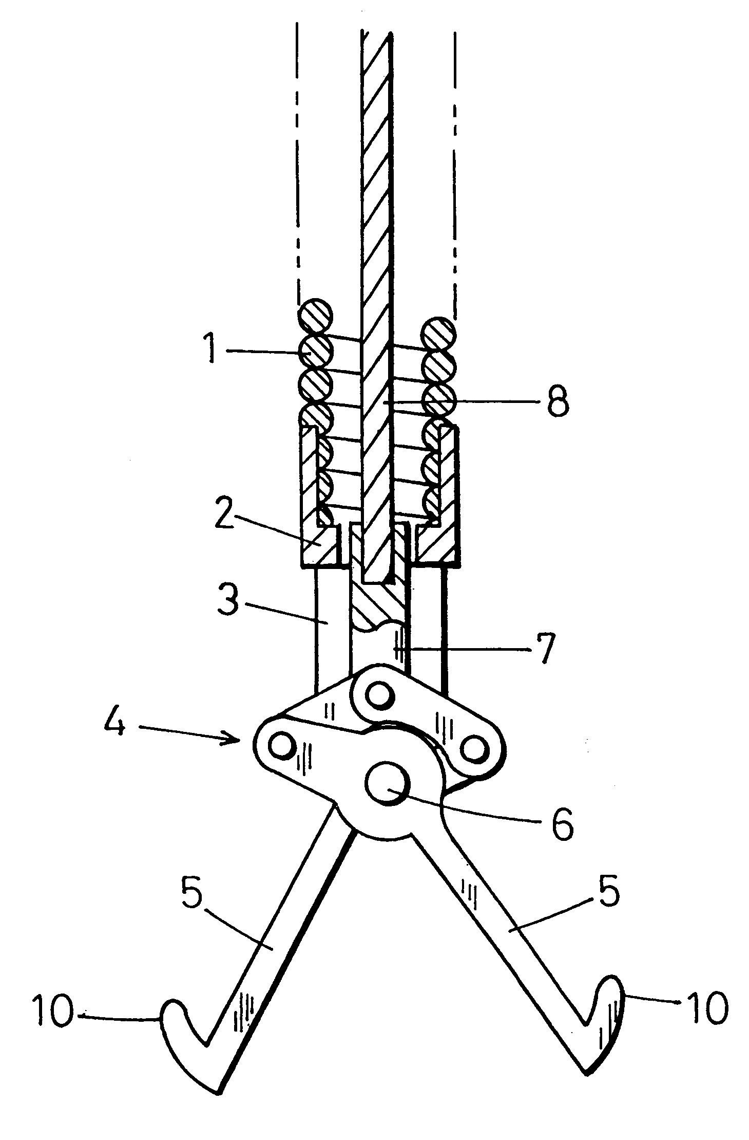
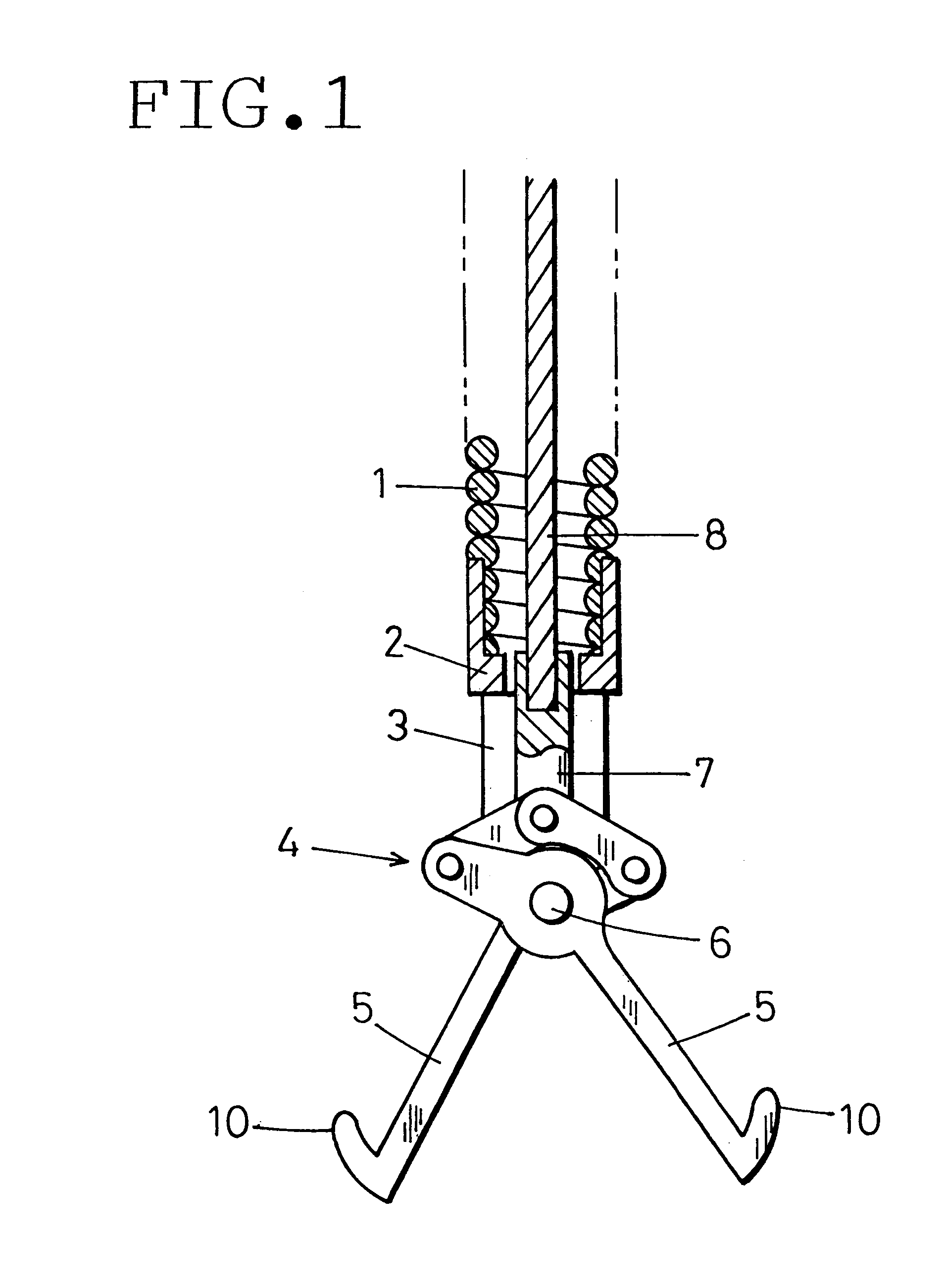
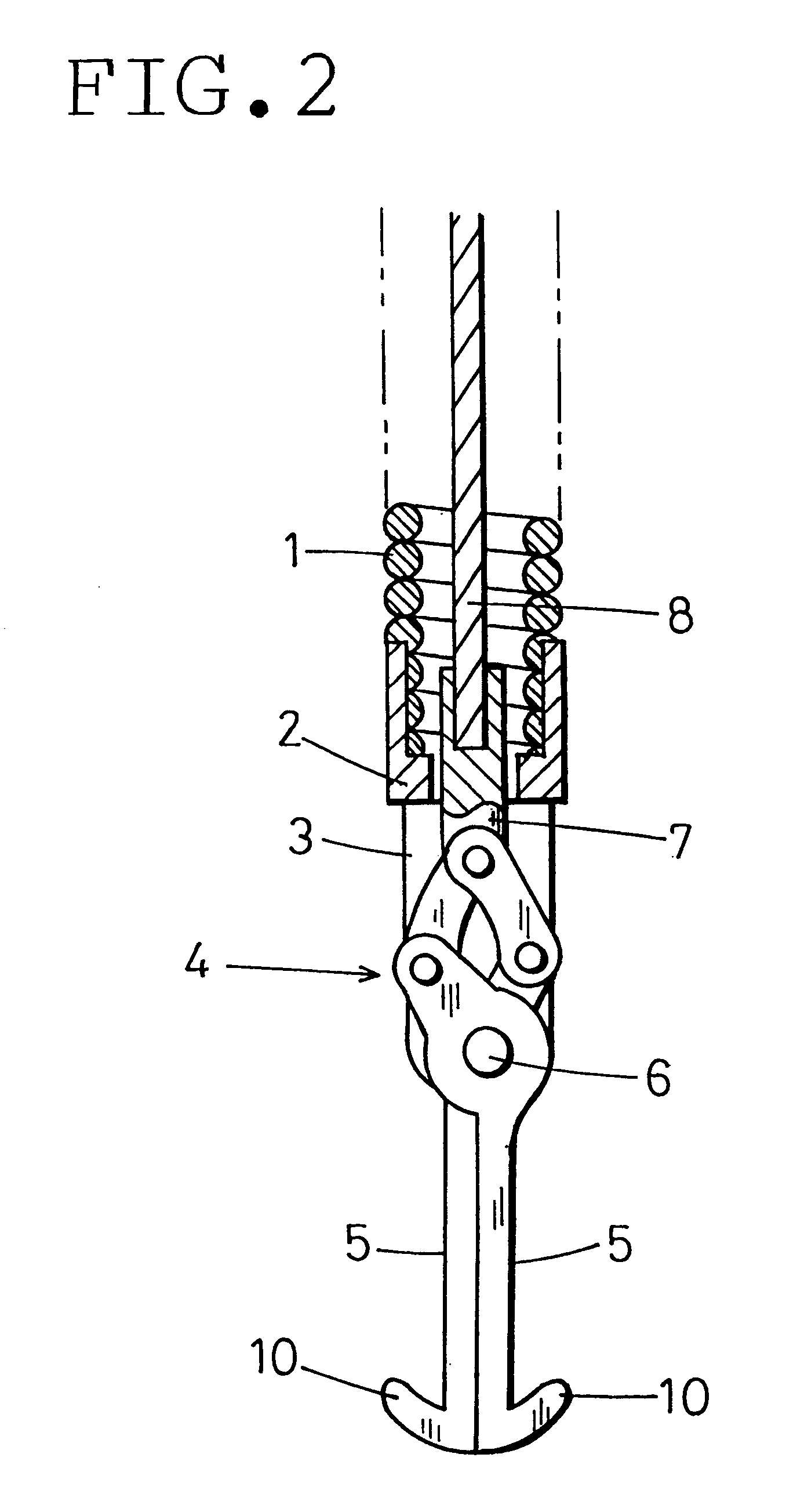
FIGS. 1 and 2 show a distal end portion of a foreign body-recovering instrument for an endoscope according to the present invention. A flexible sheath 1 is removably inserted into an instrument-inserting channel of an endoscope (not shown). A coil pipe is used as the sheath 1. The coil pipe is formed by close-winding a stainless steel wire with a uniform diameter. The sheath 1 has a diameter of the order of from 1.5 millimeters to 2 millimeters and a length of the order of from 1.5 meters to 2 meters.

A support frame 2 is rigidly secured to the distal end of the sheath 1. The support frame 2 is provided with a slit 3. A pantograph-shaped link mechanism 4 is placed in the slit 3. A pair of foreign body-catching arms 5 are connected to the link mechanism 4. The foreign body-catching arms 5 are rotatably supported by a pivot shaft 6 in the vicinity of the distal end of the support frame 2. The foreign body-catching arms 5 project forward.

A wire-connecting shaft 7 is connected to the rea...

third embodiment

FIGS. 5 and 6 show a distal end portion of a foreign body-recovering instrument for an endoscope according to the present invention. FIG. 5 shows a state where the distal end portion of the foreign body-recovering instrument is open. FIG. 6 shows a state where the distal end portion of the foreign body-recovering instrument is closed. In this embodiment, a flexible tube, e.g. a tetrafluoroethylene resin tube, is used as the sheath 1.

Four foreign body-catching arms 5 are provided at intervals of about 90 degrees as viewed from the front side (from the bottom of the figures). Each foreign body-catching arm 5 is formed from a resilient stainless steel wire or the like that is smoothly curved so as to expand outward.

It should be noted that the number of foreign body-catching arms 5 is not necessarily limited to four. For example, three foreign body-catching arms 5 may be disposed at intervals of about 120 degrees. Alternatively, two foreign body-catching arms 5 may be spaced at an angle...

fourth embodiment

FIGS. 7 and 8 show a distal end portion of a foreign body-recovering instrument for an endoscope according to the present invention. FIG. 7 shows a state where the distal end portion of the foreign body-recovering instrument is open. FIG. 8 shows a state where the distal end portion of the foreign body-recovering instrument is closed. In this embodiment, foreign body-catching arms 5 are each formed from a resilient wire. The distal end of each foreign body-catching arm 5 is bent outward at approximately right angles to form a hook-shaped engaging portion 10.

As shown in FIG. 7, the distal end half of the intermediate portion of each foreign body-catching arm 5 is bent to deflect slightly inward so that the distal end of the hook-shaped engaging portion 10 lies inside the extension A of the outer wall surface of the foreign body-catching arm 5.

Consequently, as shown in FIG. 8, the foreign body-catching arms 5 can be withdrawn into the sheath 1 completely so that the engaging portions ...


PUM


Abstract

A foreign body-recovering instrument for an endoscope in which a plurality of foreign body-catching arms are provided at the distal end of a flexible sheath so that the foreign body-catching arms are opened or closed by remote control from the proximal end of the sheath. The foreign body-recovering instrument has engaging portions serving as hooks for catching a foreign body. The engaging portions are formed on the respective outer sides of the foreign body-catching arms.

Description

The present disclosure relates to subject matter contained in Japanese Patent Application No. 10-164651 (filed on Jun. 12, 1998), which is expressly incorporated herein by reference in its entirety.1. Field of the InventionThe present invention relates to a foreign body-recovering instrument for an endoscope that is removably inserted into an instrument-inserting channel of an endoscope to recover a foreign body from a body cavity, for example, a swallowed dental crown.2. Description of the Prior ArtIn general, a foreign body-recovering instrument for an endoscope has a plurality of foreign body-catching arms provided at the distal end of a flexible sheath that is removably inserted into an instrument-inserting channel of an endoscope. The foreign body-catching arms are opened or closed by remote control conducted at the proximal end of the sheath. Each foreign body-catching arm has a claw-like portion projecting from the inner side thereof. The claw-like portion is pressed against ...

Claims


Application Information

Patent Timeline
IPC IPC(8): A61B17/22A61B17/50A61B1/00A61B17/28
CPCA61B17/22031A61B17/221A61B17/50A61B2017/22034A61B2017/22072A61B2017/2215A61B2017/2939
Inventor OUCHI, TERUO
Owner ASAHI KOGAKU KOGYO KK
Features
  • Generate Ideas
  • Intellectual Property
  • Life Sciences
  • Materials
  • Tech Scout
  • Unparalleled Data Quality
  • Higher Quality Content
  • 60% Fewer Hallucinations
Learn More