Triangular gimbal

a triangular gimbal and gimbal technology, applied in the direction of mechanical control devices, instruments, process and machine control, etc., can solve the problems of high cost, difficult manufacturing, and general complexity of the arm assembly

Inactive Publication Date: 2001-06-05
HEXEL CORP
View PDF6 Cites 74 Cited by
  • Summary
  • Abstract
  • Description
  • Claims
  • Application Information

AI Technical Summary

Problems solved by technology

Although the hexapod structure works well, the arm assemblies are generally quite complex and therefore costly and difficult to manufacture.

Method used


Image

  • Triangular gimbal
  • Triangular gimbal
  • Triangular gimbal

Examples


Embodiment Construction

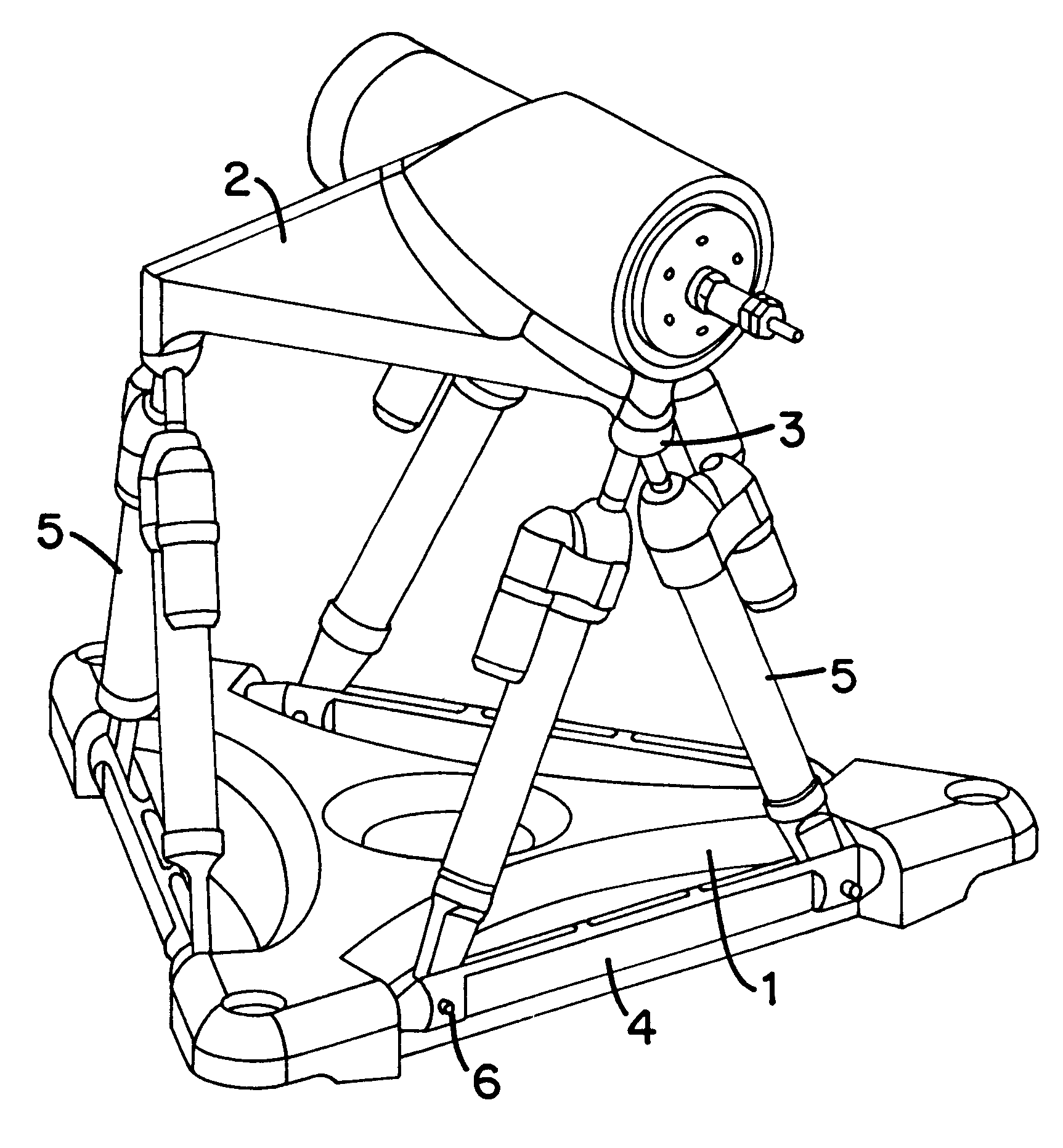
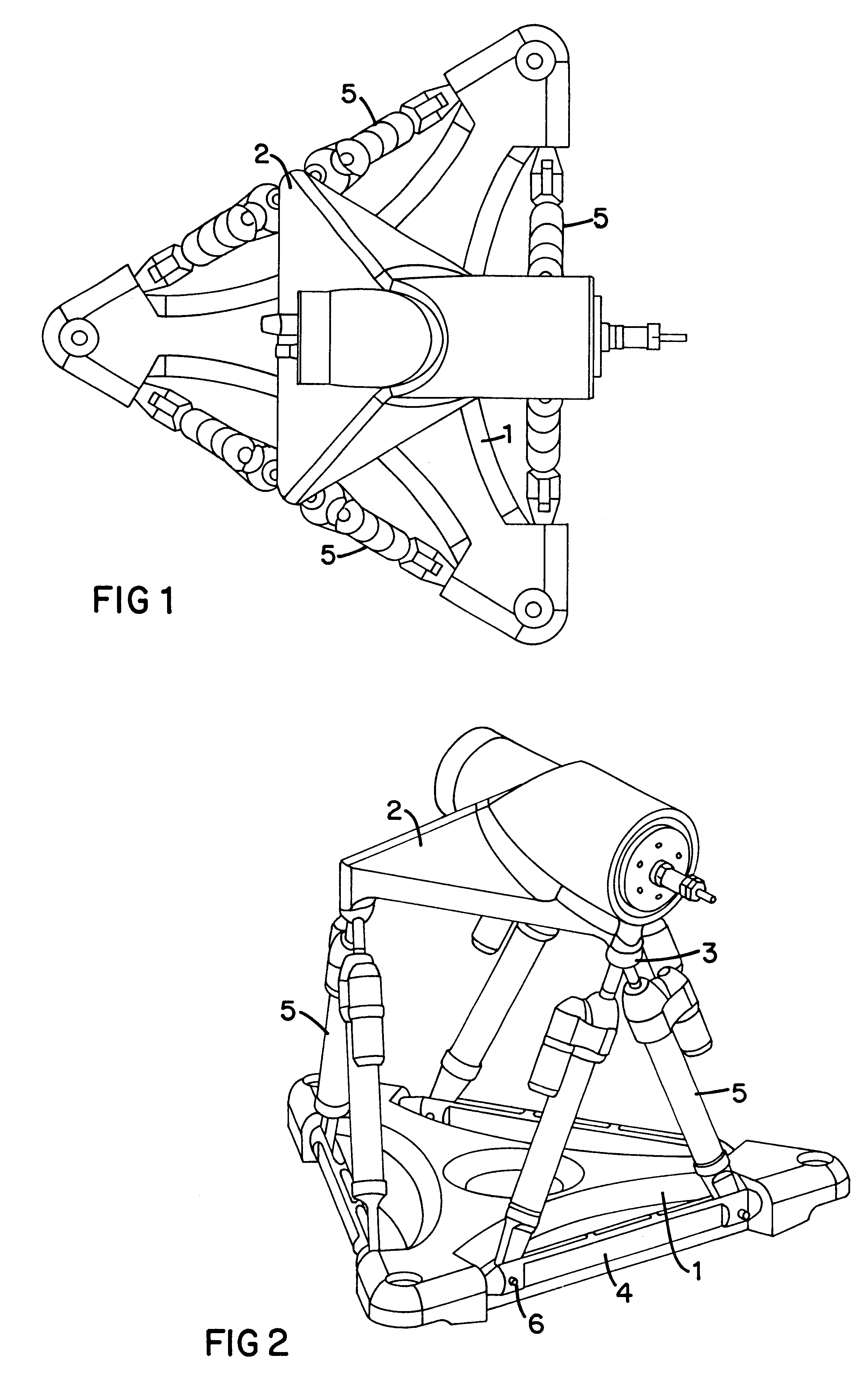
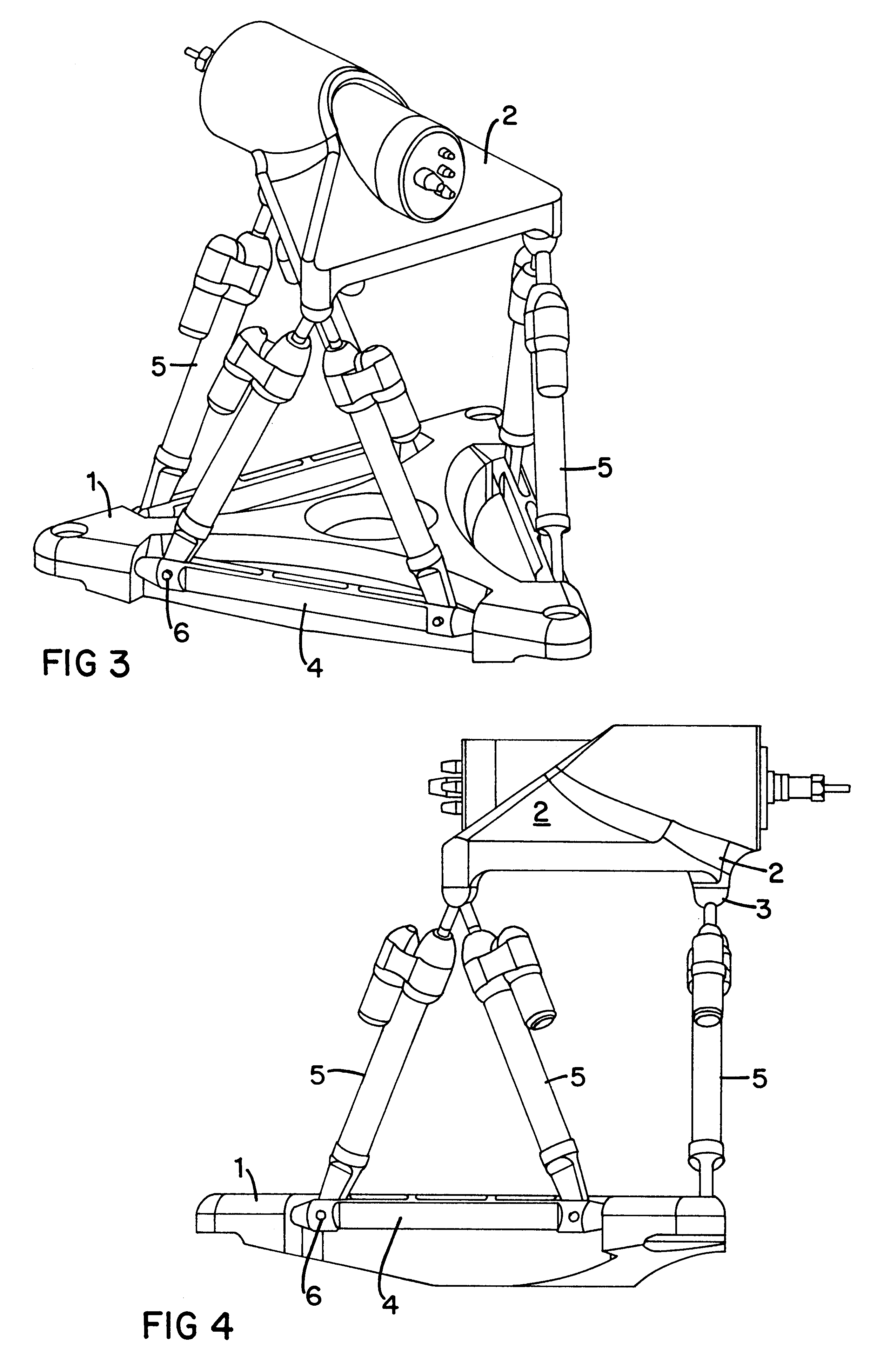
The systems and methods described herein provide triangular gimbals capable of carrying and positioning a platform in space. One embodiment of such a system is depicted in FIGS. 1-5, which show a machine 10 that includes a base 1, a platform 2, six legs 5, and a tool 12. The legs 5 of the device 10 are paired together to provide three pairs of legs, with each pair of legs forming part of a triangular gimbal that also includes a ball joint 3 that joins to the two legs at one of its ends and that joins to the platform 2 at its other end. The triangular gimbal also includes the shaft 4 that connects to both of the legs 5. Each leg 5 is pinned to the shaft 4 to hold the pin at a select location along the shaft 4. The legs are held by the pin to the shaft 4, but are free to pivot about the pin. Moreover, the shaft 4 can mount to the base 1 by couplings that allow the shaft 4 to pivot about its longitudinal axis. In the depicted embodiment, the shaft 4 constrains one axis of rotation for ...


PUM


Abstract

A system and related method to enable six-axis movement of a structure. The system is related to hexapods, Stewart platforms and other mechanical movement systems. It includes a plurality of moveable supportive legs coupled to a platform. For the Stewart platform version of the system, there are six supportive legs, each of which connects to a triangular platform that acts as a base.

Description

The invention relates to devices for manufacturing and machining, particularly devices that include a Stewart platform for positioning a tool in space.BACKGROUND OF THE INVENTION:High precision manufacturing and machining requires that the position of a tool be precisely known in space. One device developed to manipulate a tool with a high degree with accuracy is the Stewart platform. The Stewart platform, which is commonly incorporated into a hexapod manufacturing device, provides a point on the surface of a platform that can be moved with absolute certainty as long as the extension arms which move that platform have lengths which are accurately known. Therefore, the arms which are connected to the platform can be manufactured with conventional tolerances and then measured accurate. As long as the measurement made is accurate a simple equation can be employed to adjust the position of the platform and position a point on that platform at a precise and selected location. The design ...

Claims


Application Information

Patent Timeline
Patent Type & Authority Patents(United States)
IPC IPC(8): B23Q1/54B25J17/02B23Q1/25
CPCB23Q1/5462B25J17/0216Y10T74/20207Y10T74/20317
Inventor YAU, CHI LAM
Owner HEXEL CORP
Why Eureka
Try Eureka