
Transmitter/receiver having an antenna failure detection system

Inactive Publication Date: 2001-06-26
NEC CORP
View PDF14 Cites 39 Cited by
  • Summary
  • Abstract
  • Description
  • Claims
  • Application Information

AI Technical Summary

Problems solved by technology

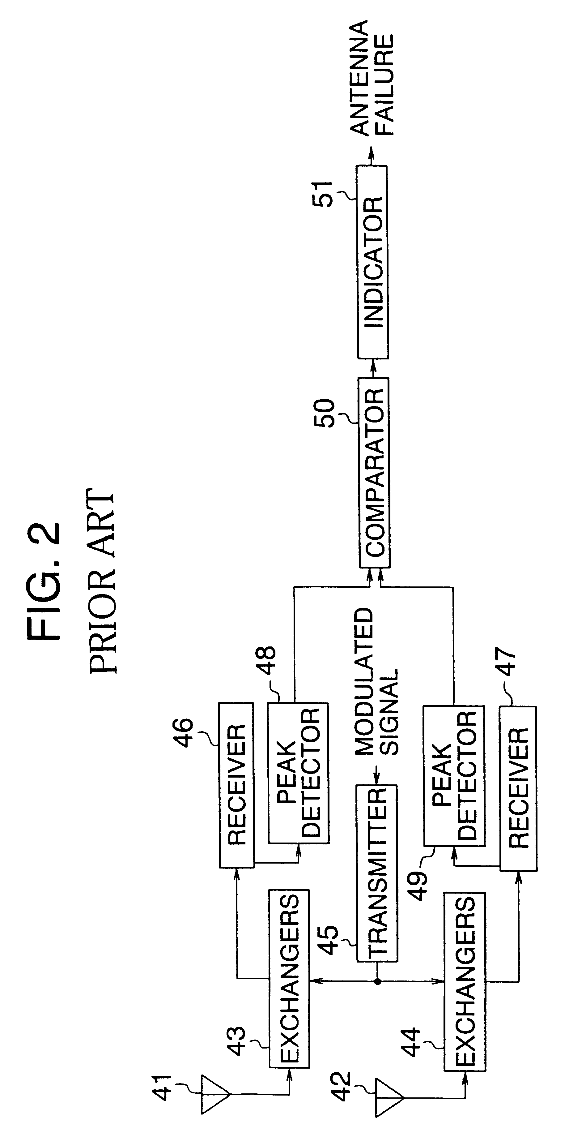
The conventional transmitter-receiver of FIG. 2 has a problem in that a real time detection of antenna failure cannot be obtained if the base station has a dedicated receiving antenna and there is no mobile station in the service area of the base station during the test operation.
This is because the base station uses a signal supplied from a mobile station which received the test signal in the service area of the base station, and the dedicated receiving antenna cannot be used for detection of reflected power by using the test signal.

Method used


Image

  • Transmitter/receiver having an antenna failure detection system
  • Transmitter/receiver having an antenna failure detection system
  • Transmitter/receiver having an antenna failure detection system

Examples


Embodiment Construction

Now, the present invention is more specifically described with reference to accompanying drawings, wherein similar constituent elements are designed by the same or similar reference numerals.

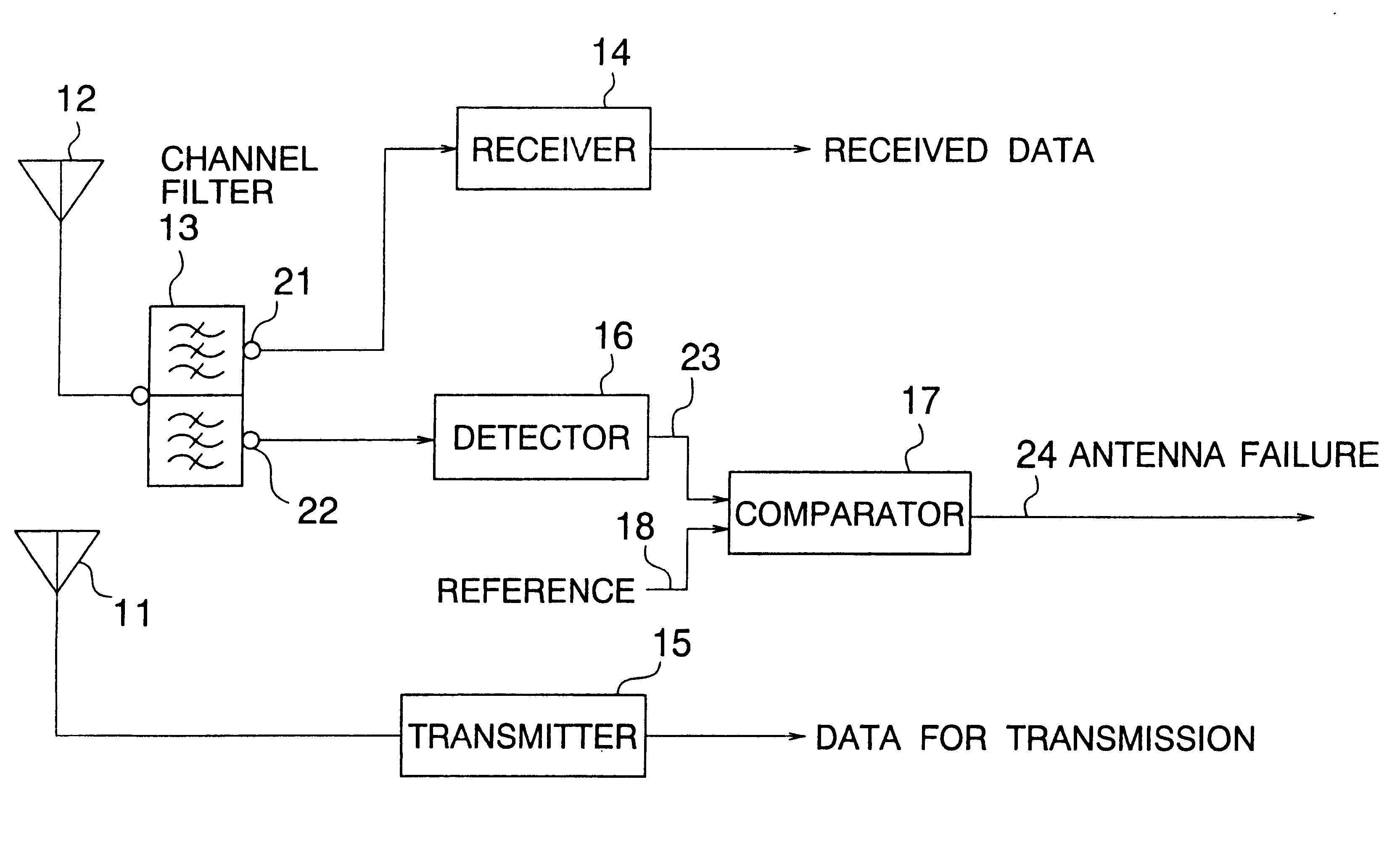
Referring to FIG. 3, a transmitter / receiver according to a first embodiment of the present invention is exemplarily implemented as a frequency domain duplex (FDD) system. The transmitter / receiver of the present embodiment comprises a transmitting antenna 11, a receiving antenna 12, a channel filter 13, a receiver 14, a transmitter 15, a detector (demodulator) 16, and a comparator 17.

The transmitter 15 converts data for transmission into a transmission signal and supplies the same through the transmitting antenna 11, which radiates the transmission signal in the air. The receiving antenna 12 catches the signals transmitted from the own station and from any mobile station staying in the service area of the base station. The channel filter 13 receives transmitted signals from the own station and mo...


PUM


Abstract

A transmitter / receiver in a base station comprises an antenna failure detection system including a receiving antenna for receiving a first signal from own station through a transmitting antenna and a second signal from another station, a channel filter for separating the first signal and the second signal, a detector for detecting the second signal, and a comparator for comparing the level of the detected signal, which is proportional to the coupling factor between the transmitting antenna and the receiving antenna, against a threshold to output an antenna failure signal based on the result of the comparison. The antenna failure detection system operates in a normal operation mode of the transmitter / receiver without reducing the number of service channels.

Description

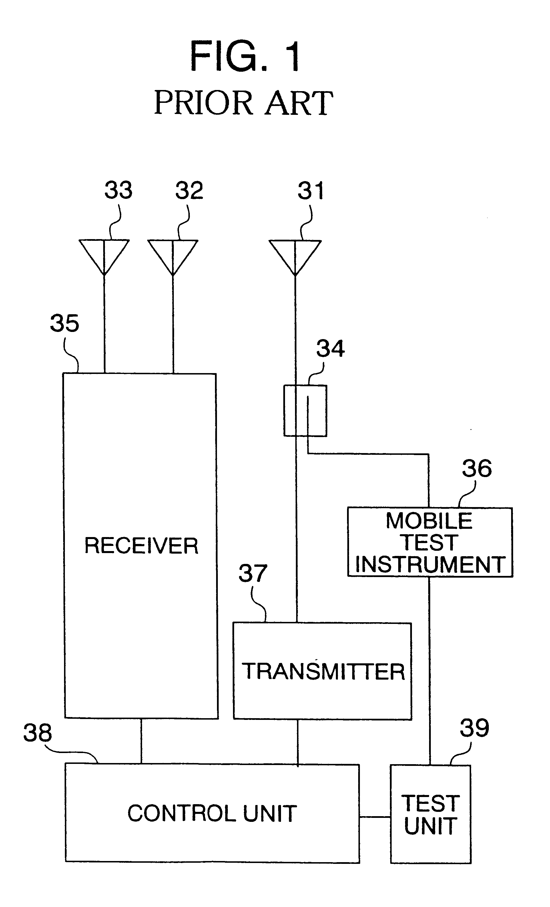
(a) Field of the InventionThe present invention relates to a transmitter / receiver having an antenna failure detection system and, more particularly, to a transmitter / receiver having an antenna failure detection system and preferably used in a base station of a mobile communication system.(b) Description of the Related ArtAn antenna failure detection system is generally used in a transmitter / receiver installed in a base station of a mobile communication system. An example of such an antenna failure detection system is described in JP-A-60-190037.FIG. 1 shows the transmitter / receiver having an antenna failure detection system described in the publication mentioned above. The transmitter / receiver comprises a transmitting antenna 31 and a pair of receiving antennas 32 and 33, a transmitter 37 for transmitting a down-signal toward a mobile station through the transmitting antenna 31, a receiver 35 for receiving through the receiving antennas 33 and 32 an up-signal from a mobile station d...

Claims


Application Information

Patent Timeline
IPC IPC(8): H04B17/00H04B1/38H04B7/26H04B17/18H04B17/29H04W24/00H04W24/08
CPCH04B17/21H04B17/19
Inventor TSUJI, KAZUSHI
Owner NEC CORP
Learn More