Hand saw having a handle including a pivoted protector for protecting a blade

Inactive Publication Date: 2001-07-03
KAPMAN
View PDF8 Cites 14 Cited by
  • Summary
  • Abstract
  • Description
  • Claims
  • Application Information

AI Technical Summary

Benefits of technology

The present invention aims at obviating the abovementioned inconveniences of previously known tools of the retractable type and at providing an improved handsaw. Therefore, in one aspect of the invention a

Problems solved by technology

In this case, however, the two handle halves are so provided that the edge portions on the two side walls defining a central gap in each half, are abutted against each other in the working position of the handle, whereby the handle is somewhat thick a

Method used


Image

  • Hand saw having a handle including a pivoted protector for protecting a blade
  • Hand saw having a handle including a pivoted protector for protecting a blade
  • Hand saw having a handle including a pivoted protector for protecting a blade

Examples


Embodiment Construction

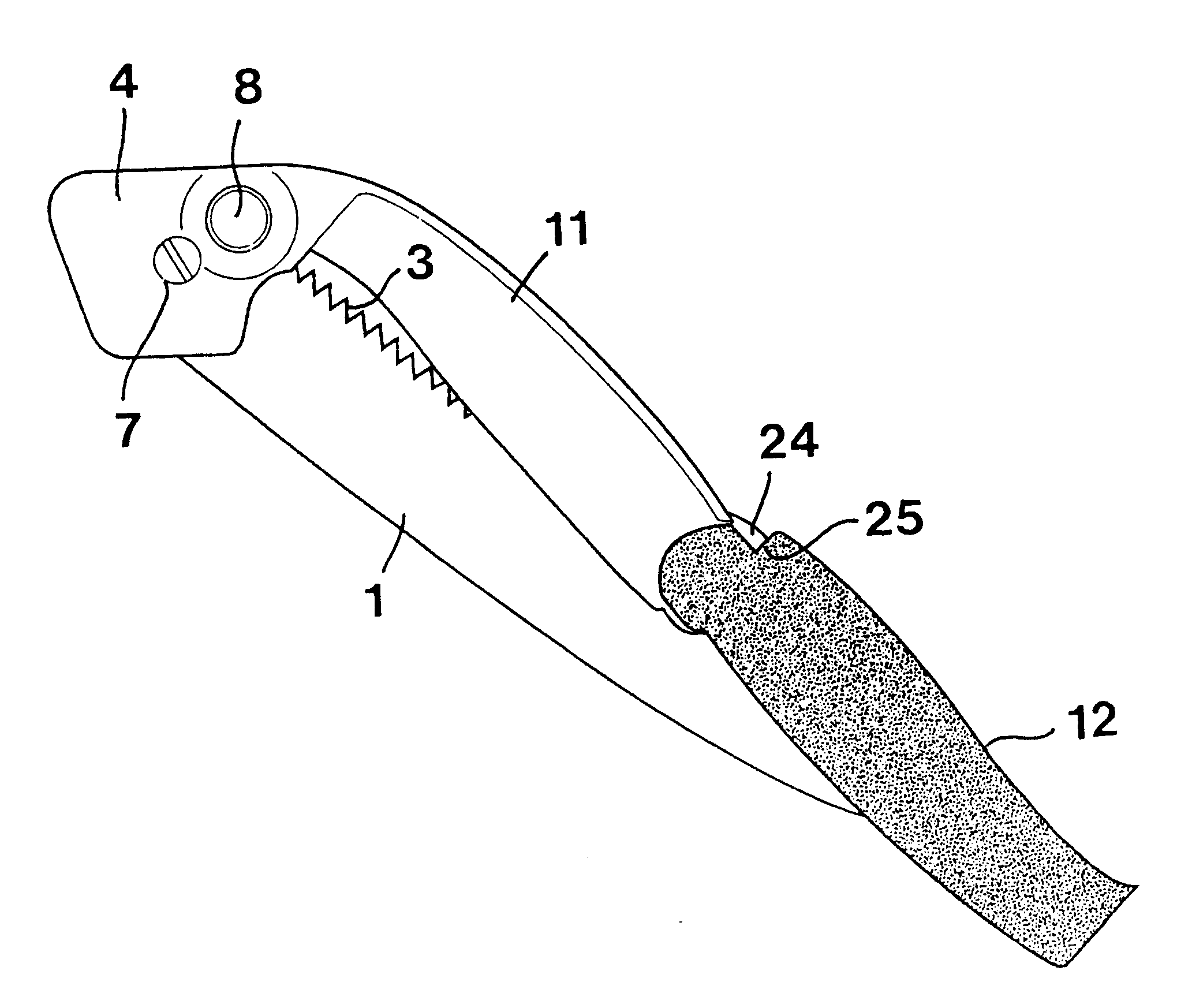
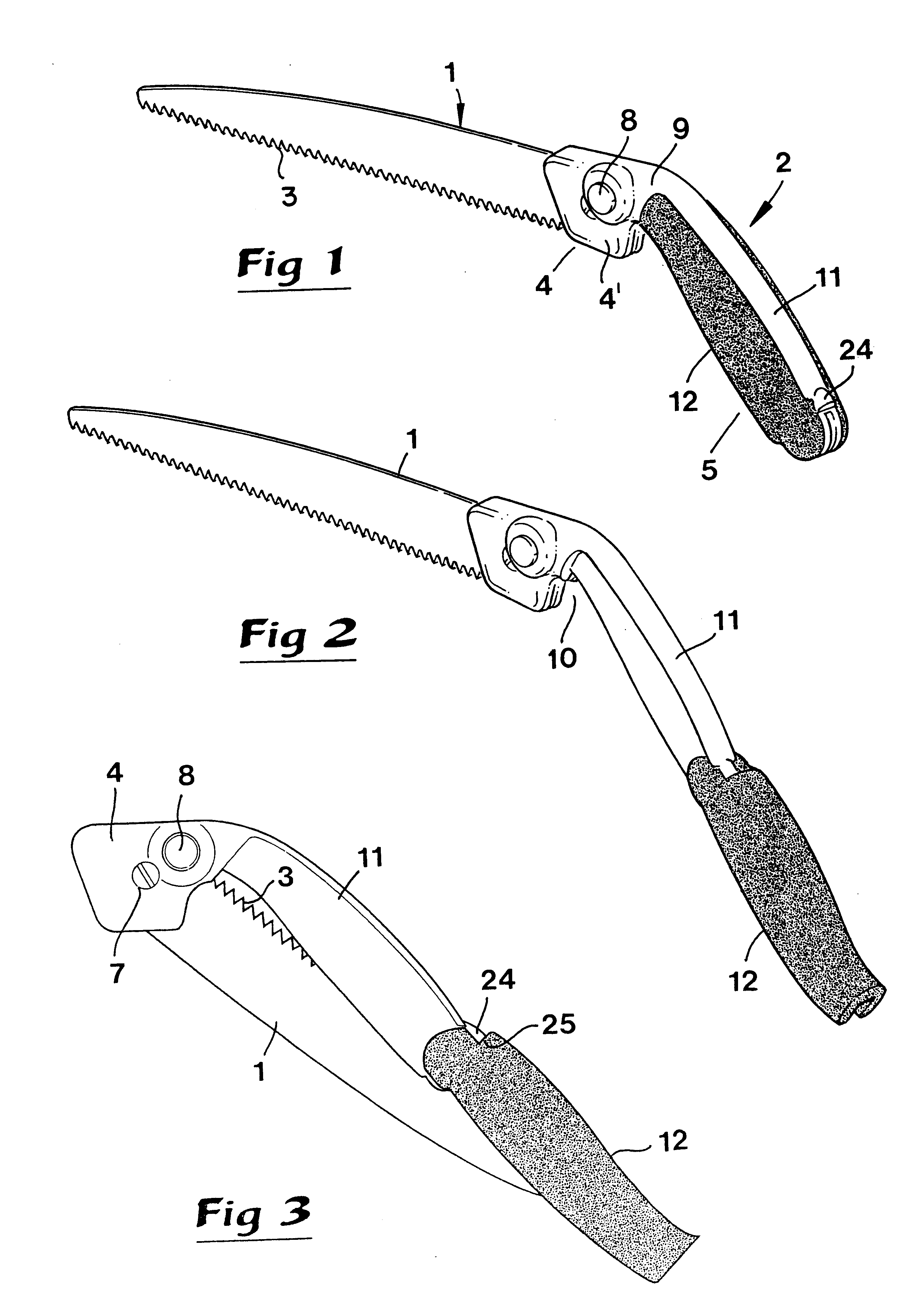
In FIGS. 1-6 a handsaw is shown, the main components of which consist of a long narrow blade 1 and a handle 2. In a known way, the cutting edge of the blade 1 includes a toothing 3 which advantageously, though not necessarily, is substantially straight. The handle 2 includes a fastening part 4 as well as a long narrow gripping part 5 which extends at an obtuse angle to the fastening part 4 and the blade 1 when the gripping part 5 assumes the working position according to FIG. 1. In practice, the angle between the gripping part 5 and the blade may be within the range of 125-150.degree..

As may be seen in FIGS. 4-6, the rear end of the blade 1 is inserted into a downwardly opening slit 6 in the fastening part 4 and connected to the part 4 via a hinge 7 which permits turning of the blade. In order to lock the blade in the working position according to FIGS. 1 and 4, a locking mechanism 8 is arranged, which is described below.

The gripping part 5 merges into the fastening part 4 via a tra...


PUM

PropertyMeasurementUnit
Angleaaaaaaaaaa
Electrical resistanceaaaaaaaaaa
Flexibilityaaaaaaaaaa

Abstract

A handsaw includes a blade having a toothed cutting edge pivoted to a handle. The handle includes a frame and a tooth protecting element. The tooth protecting element is pivoted to the frame to be swung between a working position and a retracted position. Each of the frame and the tooth protecting element includes a gap, whereby when the tooth protecting element is in a retracted position, the gaps are aligned to receive the blade. When the blade is in a retracted state, a portion of the cutting edge is exposed to enable purchasers or users to know what type of cutting edge is provided on the blade without having to move the blade to a working position.

Description

This invention relates to a handsaw. In particular a known handsaw of this type comprises a long narrow blade provided with a toothing, as well as a handle, which on one hand has a fastening part to which a rear end of the blade is connected and, on the other hand, a long narrow gripping part, which extends at an obtuse angle to the fastening part and is shorter than the blade. The blade is connected to the fastening part of the handle via a hinge which permits turning of the blade in relation to the handle between an extended position and a retracted position. A locking mechanism enables the blade to be locked in at least the extended position thereof. The gripping part is composed of a stiff frame integral with the fastening part. The frame has two side walls interconnected via a mutual back between which side walls a long narrow gap is delimited, as well as a tooth protecting element having two second side walls interconnected via a common second back. Between the second side wal...

Claims


Application Information

Patent Timeline
IPC IPC(8): B23D51/03B23D51/00B23D51/01B27B21/04
CPCB23D51/03B23D51/01
Inventor ERIKSSON, ECKHARDLINDBERG, STAFFANGARRAS, STAFFAN
Owner KAPMAN
Why Eureka
Try Eureka