Method and apparatus for a tubular skylight system

a technology of tubular skylights and skylights, which is applied in the direction of lighting and heating equipment, using daylight, transportation and packaging, etc., can solve the problems of affecting the effect of lighting,

Inactive Publication Date: 2001-07-10
SOLATUBE INT INC
View PDF82 Cites 74 Cited by
  • Summary
  • Abstract
  • Description
  • Claims
  • Application Information

AI Technical Summary

Problems solved by technology

However, installing a reflector onto the clear outer dome typically results in a large portion of the clear outer dome (i.e., approximately 1 / 3 of the surface area of the dome) being covered by the reflective material.
Moreover, when securing the outer dome to the flashing, prior art systems often incorporate screws or bolts which, upon installation or over time, tend to crack the outer dome from the point pressure.
However, because of the rigidity of prior art systems, lifting of the flashing would require the difficult disassembly of the outer dome and light tube.
Furthermore, the abutment of the lower end of the light tube on the top surface of the inner ceiling (see FIG. 1) often provides unwanted collimation of the entering sunlight rays due to the side surface of the opening in the inner ceiling.
The lower end of the light tube also sits on the plaster ring thereby substantially reducing the accessability of dust, water and bugs inside the building.

Method used


Image

  • Method and apparatus for a tubular skylight system
  • Method and apparatus for a tubular skylight system
  • Method and apparatus for a tubular skylight system

Examples


Embodiment Construction

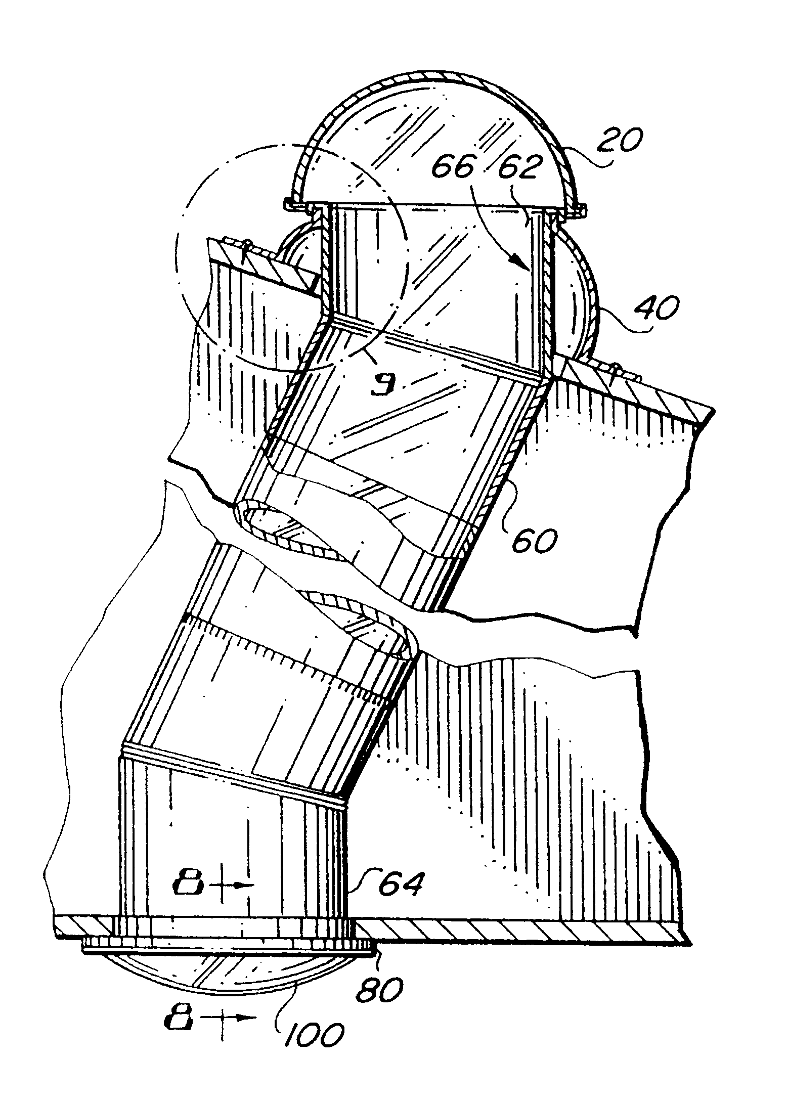
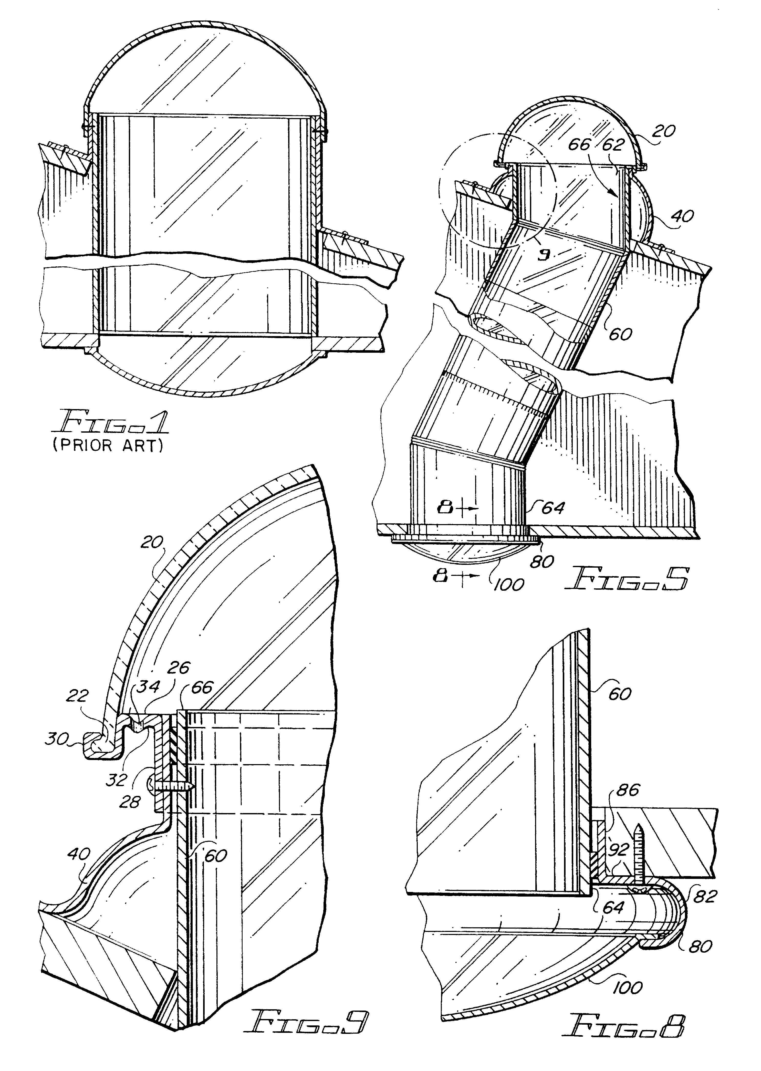
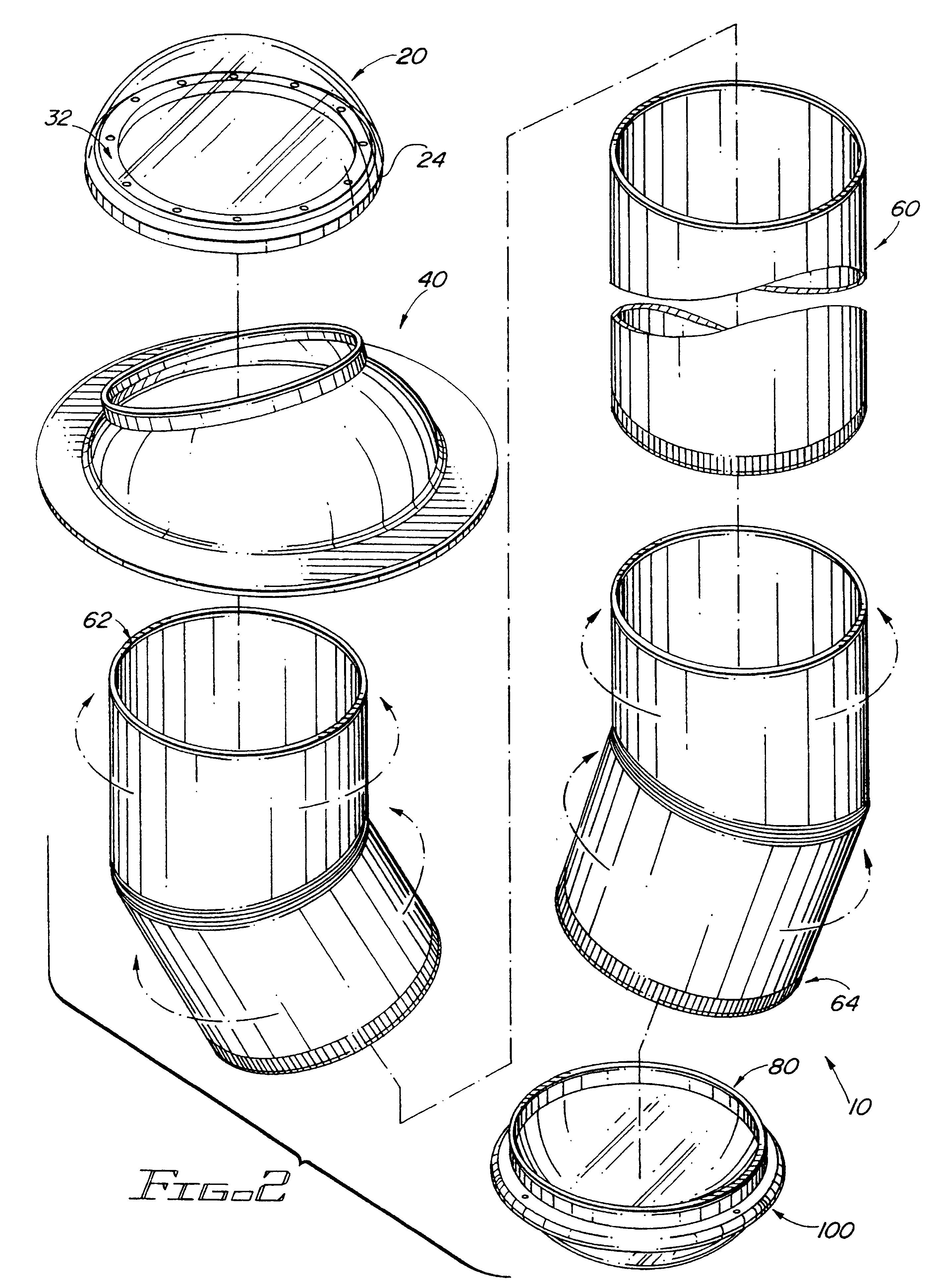
With reference to FIG. 2, the present tubular skylight system 10 preferably includes an outer dome 20, a flashing 40, a light tube 60, a plaster ring 80 and a diffuser 100. In general, in a preferred embodiment, outer dome 20 is securely directly attached to flashing 40 while first end 62 of light tube 60 is reciprocally received within flashing 40 (see FIG. 9) and second end 64 of light tube 60 rests upon, and is attached to, plaster ring 80, thereby allowing light tube 60 to "float" in flashing 40 (see FIG. 8).

More particularly, with reference to FIG. 3, outer dome 20 suitably comprises any cover capable of allowing the transmission of light rays while substantially preventing access to air, water, pests and / or the like. In accordance with a preferred embodiment of the present invention, outer dome 20 comprises a 3 / 16", G-grade or MC-grade, thermal formed, Atohaas UV stabilized clear acrylic dome 20. Outer dome 20 is preferably substantially hemispherical in shape and is preferabl...


PUM


Abstract

The present invention includes an improved tubular skylight system (10) having a clear acrylic outer dome (20), an aluminum flashing (40), an aluminum light tube (60), an aluminum ceiling plaster ring (80), and a prismatic diffuser (100). The outer dome (20) includes an aluminum ring (24) around the base (22) of the dome (20) which contains a circular channel (32) and holes (34). The aluminum ring (24) allows the outer acrylic dome (20) to be attached directly to the flashing (40) thereby substantially decreasing the risk of crack formation in the acrylic dome (20). Moreover, the surface of the acrylic dome (20) is imprinted to refract, a substantially increased amount of the natural light down into the light tube (60). The lower end (64) of the light tube (60) extends to the inside of the ceiling and sits on the plaster ring (80). The upper end (62) of the light tube (60) is reciprocally received in the flashing (40), but the outer dome (20) attaches directly to the flashing (40).

Description

The present invention relates, generally, to a method and apparatus for a tubular skylight system, and more particularly, to a method and apparatus for inputting an increased amount of outdoor sunlight, through an attic, and into a building.BACKGROUND ART AND TECHNICAL PROBLEMSIn a typical skylight arrangement, a hole is cut into a roof of a building and a clear dome is installed, thereby allowing natural light to enter the building. Incorporating a skylight system into a building which includes an attic (or other spacing between the outside of the building and the room which is to receive the light) most often requires a tubular skylight system. A tubular skylight system typically allows natural light to pass through a clear outer dome, reflect in a cylindrical light tube that spans the height of the attic space, then enter the room through a diffuser (see FIG. 1).During the summer months, in most places, an adequate amount of light enters the skylight system because the sun is sub...

Claims


Application Information

Patent Timeline
Patent Type & Authority Patents(United States)
IPC IPC(8): E04B9/00E04D13/03E04B9/32
CPCE04B9/32E04D13/0305F21S11/00E04D13/033E04D2013/0345
Inventor GRUBB, DENNIS
Owner SOLATUBE INT INC
Why Eureka
Try Eureka