Web handling apparatus

a technology of handling apparatus and web, which is applied in the direction of pile separation, projectors, cameras, etc., can solve the problems of affecting the quality of the difficulty of properly projecting the web or lead strip from the downstream end of the apparatus, and the problem of lightweight tissue still giving problems, etc., to achieve the effect of prolonging the guiding tray

Inactive Publication Date: 2001-08-07
VOITH PATENT GMBH
View PDF3 Cites 4 Cited by
  • Summary
  • Abstract
  • Description
  • Claims
  • Application Information

AI Technical Summary

Benefits of technology

A further improvement may be achieved by a second air slot arranged at the downstream end of the guiding tray, e.g. between the metal plate and an auxiliary plate arranged parallel to the metal plate, e.g., similar to German Utility Model G 91 09 313.9. The auxiliary plate may extend beyond the downstream end of the guiding tray and can be effective as a prolongation of the guiding tray.

Problems solved by technology

However, lightweight tissues still give problems.
Lightweigt tissue has been found to fall over the end of the shoe out of control.
The improved apparatus works well in most circumstances but is has been found that as the velocity of the paper-making or paper-finishing machines is increased up to more than 2000 meters per minute, it becomes more and more difficult to properly project the web or lead strip from the downstream end of the apparatus to the following structure or to the following section of the machine.

Method used


Image

  • Web handling apparatus
  • Web handling apparatus

Examples


Embodiment Construction

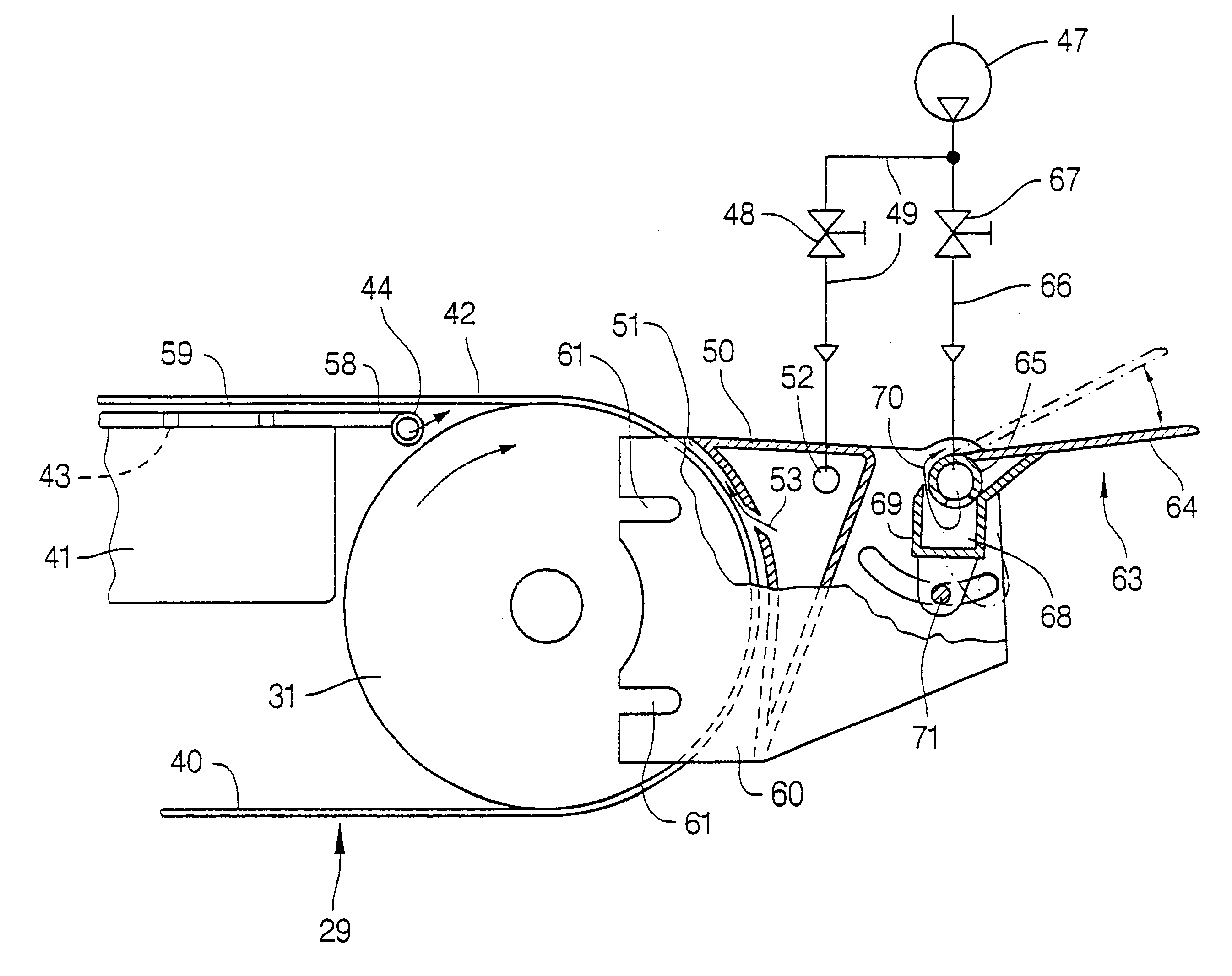
The conveyor designed according to the present invention comprises an endless belt 29 that extends between a pair of belt pulleys, namely a first (upstream) pulley, not shown and a second (downstream) pulley 31. Belt tensioners are provided which are of known construction and are not therefor described here. The side frames are connected to the vertical sides of an enlongated chest 41. Chest 41 is located between the lower run 40 of the belt 29 and its upper run 42. Chest 41 extend longitudinally of the conveyor belt 29 between said pulleys. The chest has a perforated wall located adjacent to and parallel to one of the belt runs. With the illustrated design, the perforated wall is adjacent to the upper run 42 of the belt. An opposite design may also be provided. The perforations may take any desired form, for example, holes 43. The chest 41 is also provided with a conduit which is connected by suitable air line to a vacuum pump.

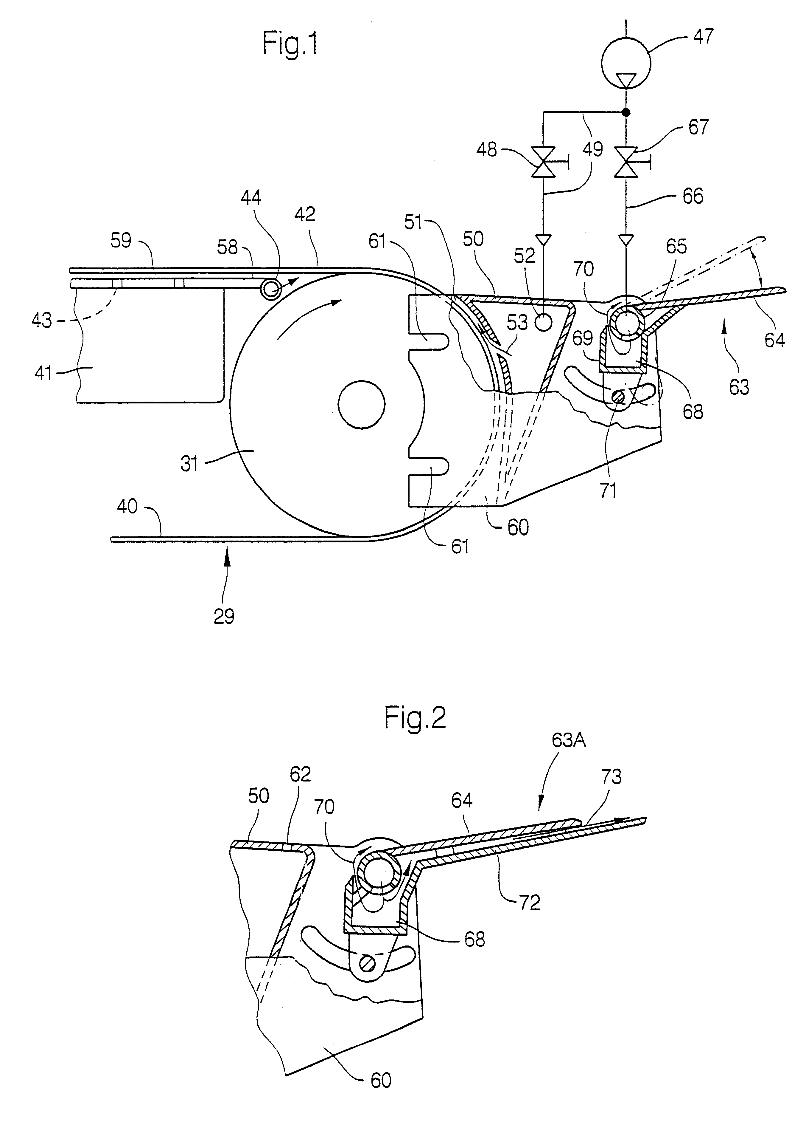
Beyond the second pulley 31, a "nose shoe" or discharge...


PUM


Abstract

An apparatus and process for transporting at least a portion of a web of flexible material between first and second structures spaced from each other. The apparatus includes at least two pulleys located at spaced locations from each other, and an air-pervious endless belt movably mounted on the first and second pulleys. The belt has a run traveling from the first pulley, adjacent the first structure, to the second pulley, adjacent the second structure, and the belt is adapted and arranged to receive the at least a portion of the web from the first structure. An underpressure source is arranged to produce an underpressure adjacent to the run of the endless belt. A nose shoe is disposed beyond the second pulley and spaced from the second pulley, so as to define an opening between the nose shoe and the second pulley at a second position where the at least a portion of the web leaves the endless belt. The nose shoe includes an inlet adapted to receive a supply of air, and air jet outlet positioned adjacent the second pulley, and the air jet outlet is adapted to direct at least one air jet into the opening in a direction contrary to a rotation of the second pulley, such that the at least one air jet is sufficient to lift the at least a portion of the web from the endless belt. A guiding tray is arranged beyond the nose shoe having an upstream section positioned adjacent the nose shoe, and the upstream section includes an air slot, which extends cross-wise to a web travel direction, adapted for emitting an air curtain that flows along the surface of the guiding tray. The process includes transferring the at least a portion of the web from the first structure onto the endless belt, holding the at least a portion of the web onto the endless belt through the underpressure, directing air from the air jet outlet through the opening in a direction against a rotational direction of the second pulley, transferring the at least a portion of the web from the endless belt to the nose shoe, and directing an air curtain from the upstream section of guiding tray along a surface of the guiding tray, such that the at least a portion of the web is guided over the guiding tray.

Description

1. Field of the InventionThis invention relates to an apparatus for transporting a web of a flexible material between a first and a second position. In particular, and in a preferred embodiment, the invention provides an apparatus, known as a "vacuum conveyor", for transporting a web, preferably a lead strip of a paper web from the dryer of a paper-making machine to the first nip of a calender of the machine or to a winding machine or between any other sections of a paper-making or paper-finishing (e.g. coating) machine.The present invention is intended as an improvement over the operation of the apparatuses described in U.S. Pat. Nos. 3,355,349 and 4,022,366. All features disclosed in these patents are incorporated into the present patent application by reference.2. Discussion of Background InformationU.S. Pat. No. 3,355,349 issued on Nov. 28, 1967 describes an apparatus for transporting a lead strip of paper web from the dryer of a paper-making machine and feeding into the first r...

Claims


Application Information

Patent Timeline
Patent Type & Authority Patents(United States)
IPC IPC(8): B65H20/10D21G9/00
CPCD21G9/0063B65H20/10
Inventor HILL, TONYMOHRSEN, LEIF
Owner VOITH PATENT GMBH
Why Eureka
Try Eureka