Pipe connector

Inactive Publication Date: 2001-11-06
HOSHINO GAKKI COMPANY LIMITED
View PDF2 Cites 33 Cited by
  • Summary
  • Abstract
  • Description
  • Claims
  • Application Information

AI Technical Summary

Problems solved by technology

Moreover, it is disadvantageous from an appearance viewpoint if the screw part 101 of the tightening member 100 is exposed from the main holding body 96.

Method used


Image

  • Pipe connector
  • Pipe connector
  • Pipe connector

Examples


Embodiment Construction

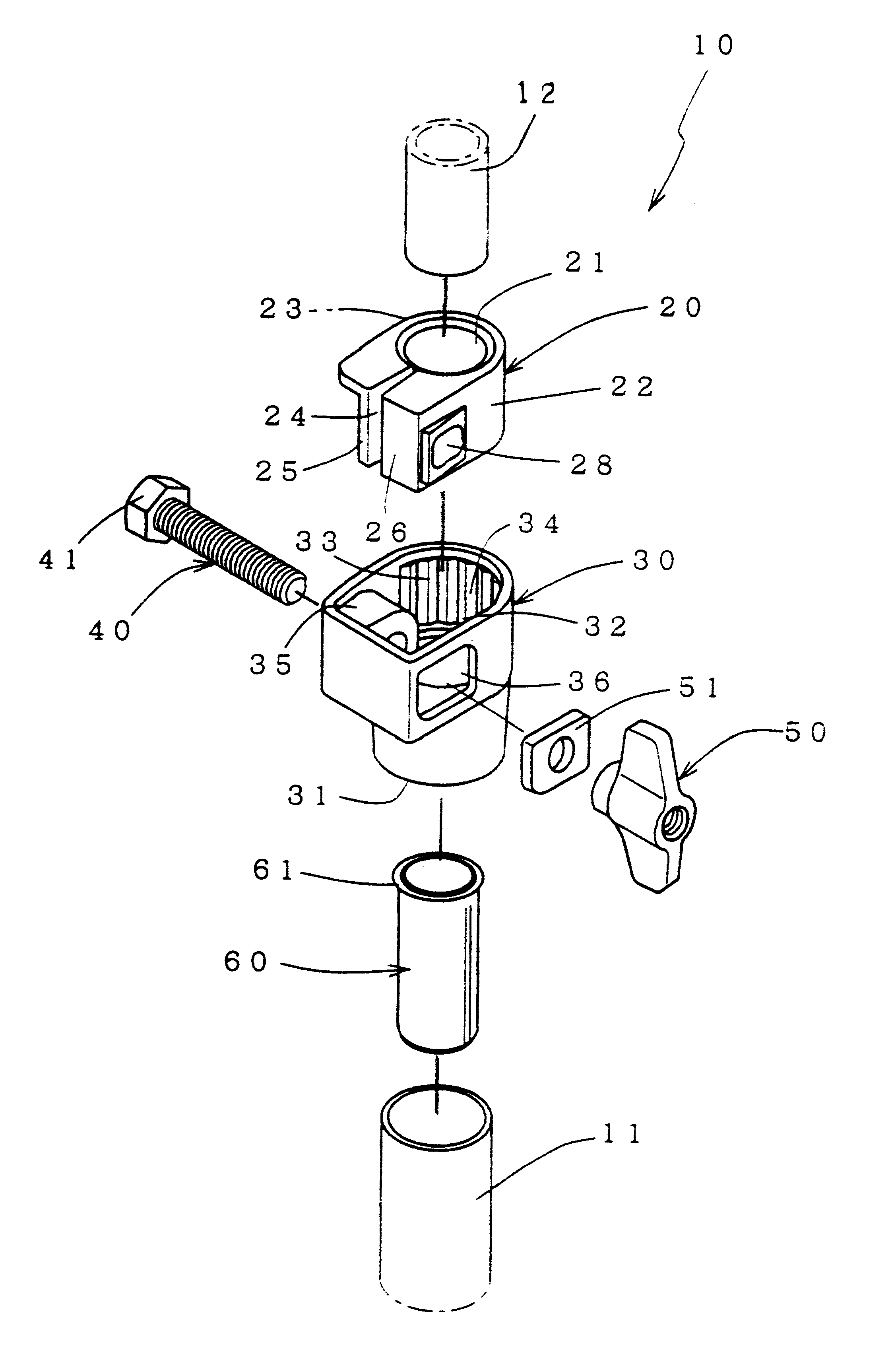
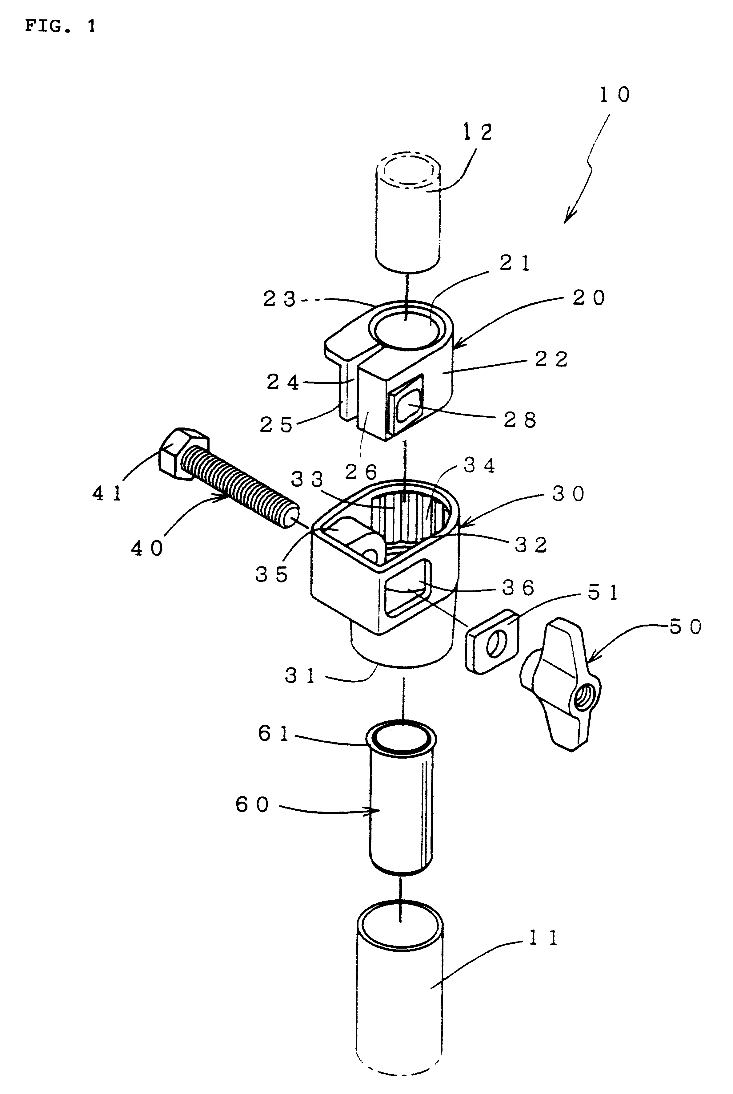
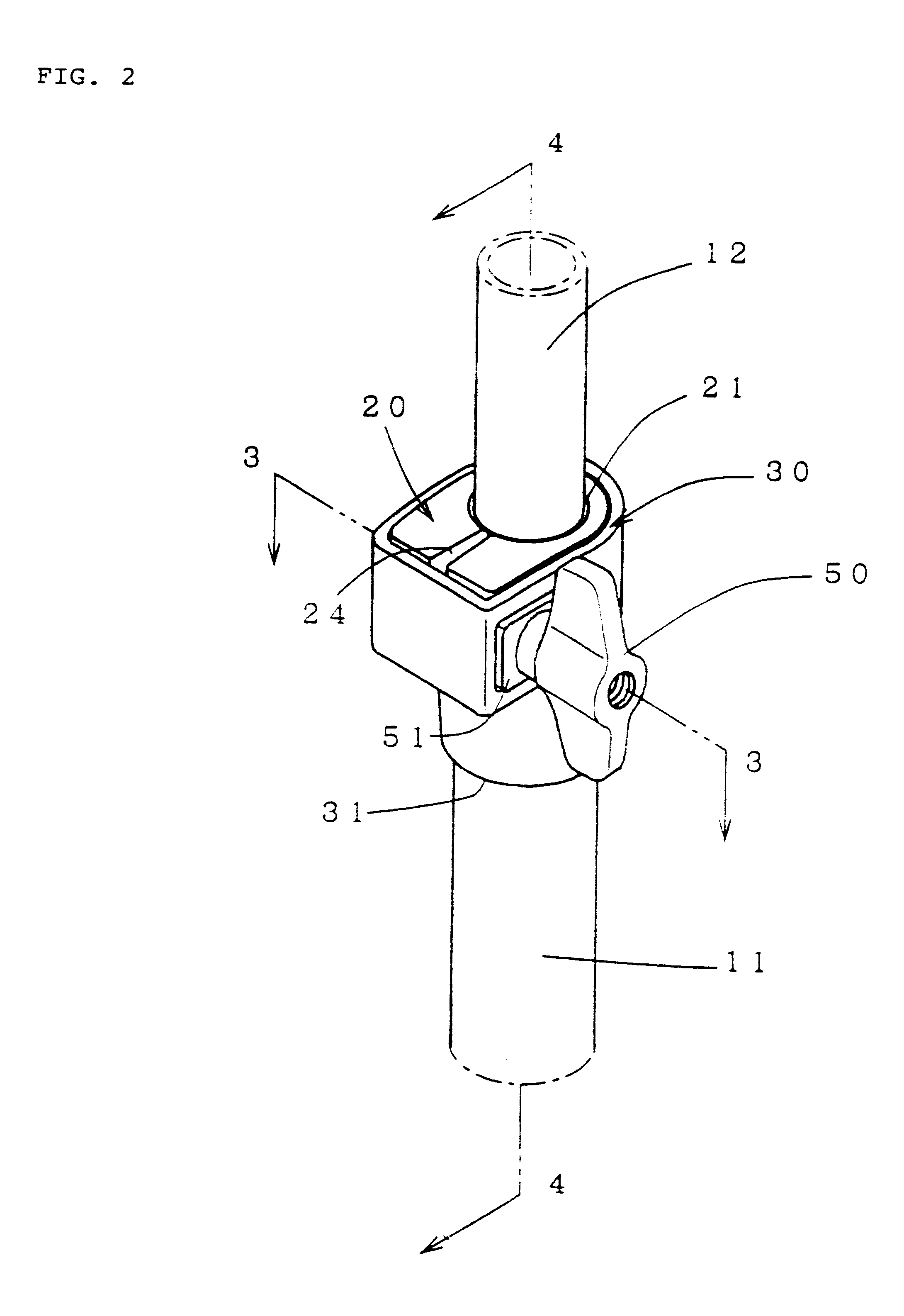
The pipe connector 10 according to the invention is for connecting a large diameter pipe 11 and a small diameter pipe 12, as shown in FIGS. 1 and 2. The connector comprises a tightening bush 20 for securing the small diameter pipe 12, a main holding body 30 which receives the bush 20 from above and receives the large diameter pipe 11 from below, a tightening bolt 40 and a cooperating tightening nut 50. As an example, the holding device is used in a cymbal stand as shown in FIG. 6.

The tightening bush 20 has a tubular body with a small diameter pipe holding hole 21 that holds the small diameter pipe 12. One circumferential region around the exterior periphery of the bush 20 has formed on it a plurality of raised ribs or splines 23 that extend in the tubular or axial direction (FIGS. 3 and 4). In addition, the bush is completely cut through radially at 24 in the tubular direction defining cut edges 25 and 26 which face each other and sandwich the cut 24. The cut 24 extends into the sma...


PUM


Abstract

To connect a large and a small diameter pipe, a pipe connector has a tightening bush with a cut through it and is compressed around the pipe and has a main body with a receptacle for the tightening bush. The tightening bush has first axial ribs on a circumferential region of the periphery. The main body receptacle has cooperating complementary second internal ribs engaged by the first ribs so that as the bush is tightened, it does not rotate in the receptacle. A large pipe holder extends down from the receptacle for the bush and receives the large diameter pipe. An auxiliary bush may be disposed inside the large pipe in the radial space between the large and small diameter pipes.

Description

This invention relates to a pipe connector for connecting a large diameter pipe with a small diameter pipe.DESCRIPTION OF A PRIOR ART EMBODIMENTA known cymbal stand 80, shown in FIG. 6 for example, includes a pipe holder 90 that holds a smaller diameter pipe 84 in a larger diameter pipe 83 or a smaller diameter pipe 83 in a larger diameter pipe 82, for connecting and holding them in a freely telescopable, expandable and contractable manner.The pipe connector 90 in FIG. 7 comprises a split ring tightening bush 91, a main holding tool and receptacle 96, and a tightening member 100, for tightening the arms of the bush over an installed pipe.The split ring tightening bush 91 is an approximately C-shaped tubular body cut through one side at 92. The cut 92 is defined by edges 93 and 94. A small diameter pipe 83 is inserted into and held in the bush 91.The main holding body 96 has a tubular, large diameter pipe receiver 97 on one axial side that encases and holds the outer periphery of the...

Claims


Application Information

Patent Timeline
Patent Type & Authority Patents(United States)
IPC IPC(8): F16B7/00F16B7/14G10D13/00G10D13/06G10G5/00
CPCF16B7/1418Y10T403/69Y10T403/7077Y10T403/32426Y10T403/7062
Inventor HOSHINO, YOSHIHIRO
Owner HOSHINO GAKKI COMPANY LIMITED
Why Eureka
Try Eureka