Backset adjustment structure of dead bolt assembly for door lock

a dead bolt and assembly technology, applied in the direction of building locks, constructions, fastening means, etc., can solve the problems of reducing the yield in mass production, high production costs, and difficult for users to adjust the backset distan

Inactive Publication Date: 2001-11-20
HYUNDAE DL
View PDF6 Cites 44 Cited by
  • Summary
  • Abstract
  • Description
  • Claims
  • Application Information

AI Technical Summary

Problems solved by technology

However, these conventional structures are complicated to cause high production costs, and handling for backset adjustment is not easy and takes time thereby decrea

Method used


Image

  • Backset adjustment structure of dead bolt assembly for door lock
  • Backset adjustment structure of dead bolt assembly for door lock
  • Backset adjustment structure of dead bolt assembly for door lock

Examples


Embodiment Construction

Reference will now be made in detail to the preferred embodiments of the present invention, examples of which are illustrated in the accompanying drawings.

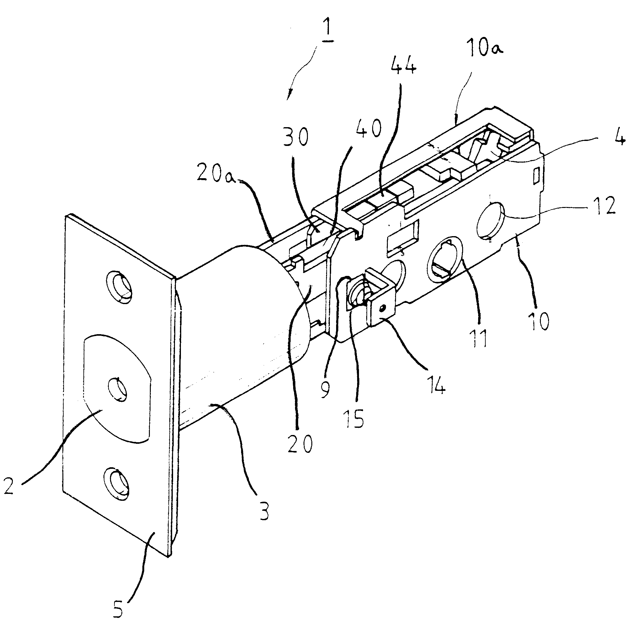
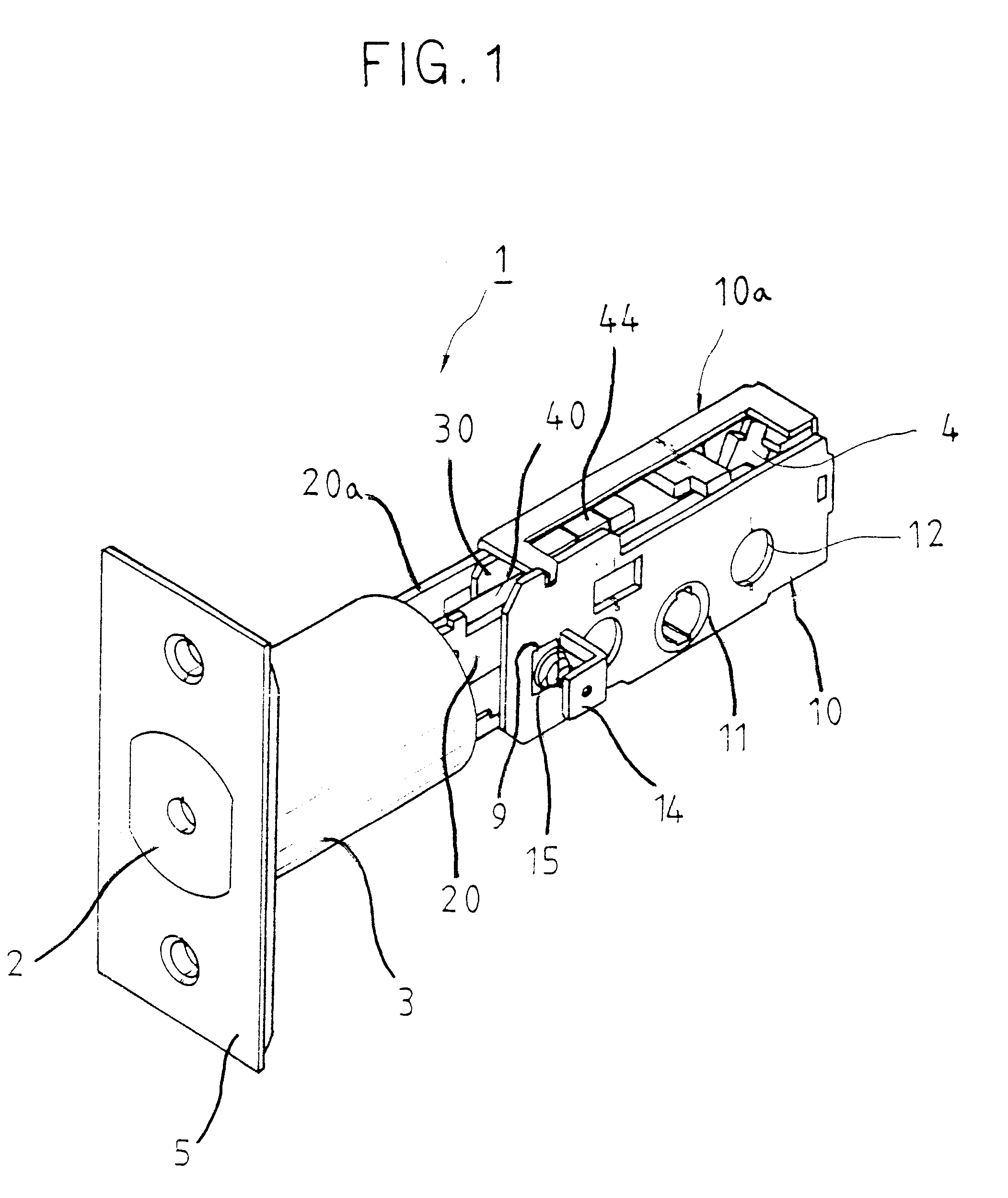
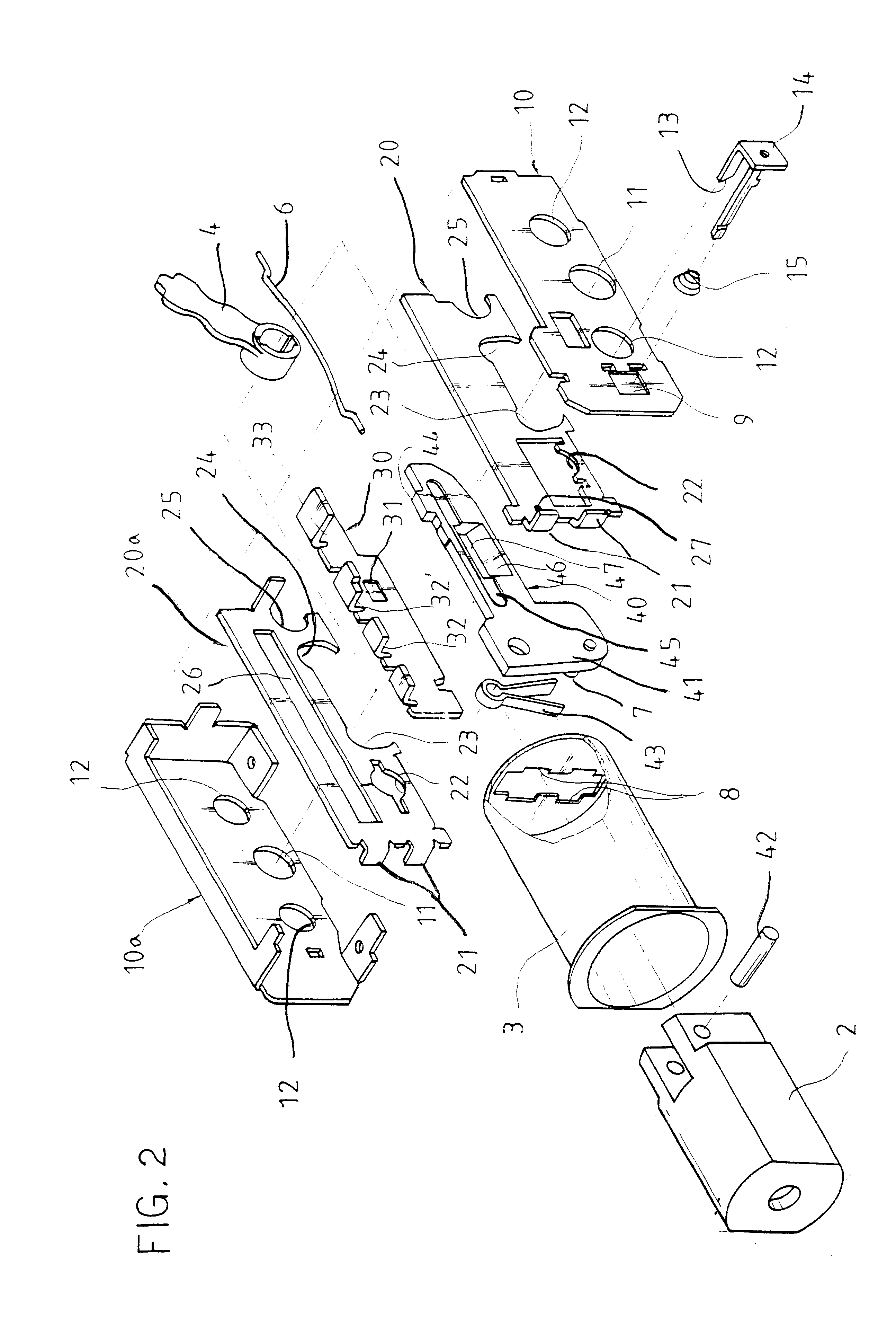
A dead bolt assembly 1 includes a part of which a dead bolt 2 is inserted into a support tube 3 and is moved forward and backward, and a main body for backset adjustment. More particularly, dead bolt assembly 1 has cover plates 10 and 10a at its front and rear parts, two support plates 20 and 20a in cover plates 10 and 10a, and a catch plate 30 and an operating plate 40 in the middle.

Each of both cover plates 10 and 10a has a hole 11 for installation of an operating lever 4 into which a door lock lever's working shaft (not shown) is inserted to move dead bolt 2 forward and backward, and a hole 12 used for coupling the overall door lock to a door.

As both cover plates 10 and 10a are joined to each other, the overall dead bolt assembly 1 is completely coupled. Each of support plates 20 and 20a, installed in cover plates 10 and 10a, h...


PUM


Abstract

A backset adjustment structure for a dead bolt assembly having a dead bolt connected with an operating plate, a support tube connected to support plates, and an operating lever operating the dead bolt, including cover plates enclosing the support plates and each having a hole for receiving the operating lever; a catch plate installed next to the operating plate to be moved along with the cover plates, and having catch grooves in which a given sized catch boss, provided to the operating plate, is fitted; the operating plate having a front end connected with the dead bolt by a pin and able to be turned down, and a space with a slant at its middle; and a button with a protruded slant formed on one of the cover plates, and operating to turn the operating plate down.

Description

1. Field of the InventionThe present invention relates to a backset adjustment structure of a dead bolt assembly provided to a door for locking the door which can adjust a backset distance to 60 mm or 70 mm in a convenient manner.2. Discussion of Related ArtIn order to provide a door lock to a door, an installation hole should be formed on the door, and a distance from the door's end to the installation hole's center is formed to one of two standards: 60 mm or 70 mm. Therefore, the dead bolt assembly has a backset adjustment structure, and according to a conventional structure disclosed in Utility Model Registration No. 83799 and Patent No. 104703 granted to the present applicant, a dead bolt and a bolt head are turned by about 45.degree. and pushed or pulled, and then 45.degree. turned to the original position for the backset adjustment. In another way, the screwy turning has been used for backset adjustment. However, these conventional structures are complicated to cause high prod...

Claims


Application Information

Patent Timeline
IPC IPC(8): E05B63/00E05B63/06
CPCE05B63/06E05B63/0017Y10T292/06Y10T292/62E05B15/00
Inventor KANG, EUI SHIK
Owner HYUNDAE DL
Why Eureka
Try Eureka