Stabilized precoder for data transmission

Inactive Publication Date: 2001-11-27
ADAPTIVE BROADBAND
View PDF8 Cites 53 Cited by
  • Summary
  • Abstract
  • Description
  • Claims
  • Application Information

AI Technical Summary

Problems solved by technology

In particular, the signal amplitude at the receiver is distorted, and this causes the automatic gain control (AGC) level to vary due to signal level fluctuations.
Without synchronisation the receiver has difficulty in distinguishing between `spikes` (due to tra

Method used


Image

  • Stabilized precoder for data transmission
  • Stabilized precoder for data transmission
  • Stabilized precoder for data transmission

Examples


Embodiment Construction

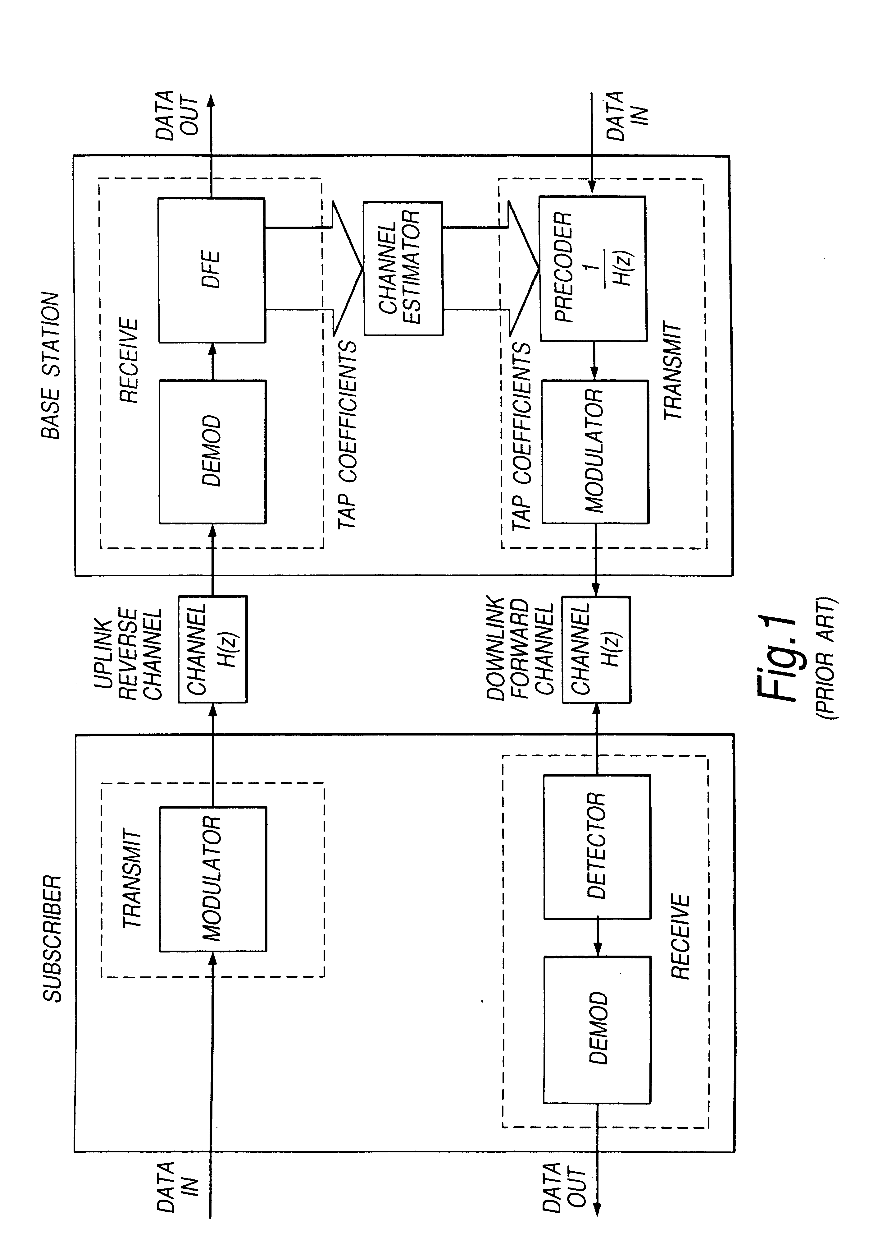
A communications system according to a first embodiment of the present invention with the equalizer and precoder located in the subscriber terminal is shown in FIG. 3.

On the downlink the base station (1) transmits data to the subscriber terminal (2). Data symbols (3) are input to the base station transmitter, where they pass into a modulator (4). The modulator converts the data into a radio signal for transmission (5). This radio signal is transmitted over the downlink channel (6), and arrives as a distorted signal (7) at the subscriber (2). At the subscriber, the received signal (7) is demodulated by a demodulator (8), and then passed into a decision feedback equalizer (DFE) (9). The DFE removes any ISI from the signal and outputs a set of data symbols (10). At the end of a received data burst, the channel characteristics (11) measured by the DFE in the form of the DFE feedforward (FF) and feedback (FB) filter coefficients B=[b.sub.1, b.sub.2, . . . ,b.sub.p ]. may be passed direct...


PUM


Abstract

A precoding scheme for digital data transmission across multipath channels is described, which improves on existing methods of precoder stability. This precoding scheme uses radial reduction of unstable roots to stabilize the precoder. Furthermore, in a broadband access system in which the preceding scheme is used, all of the precoding and equalization is performed in the subscriber units. This eliminates the problems of equalization and training delays occuring at the base station, thus allowing rapid demodulation of data arriving at the base station for several disparate subscriber terminals units.

Description

The present invention from a first aspect relates to a stabilization technique for precoders of the type used in data communications systems. In particular, the present invention is concerned with stabilizing the precoder in a robust manner by operating upon the transfer function of the precoder filter.Furthermore, from a second aspect the present invention relates to a point-multipoint data communications system wherein data equalization and precoding is performed in the subscriber terminals.In radio communications systems, the transmitted signal travels from transmitter to receiver over a channel consisting of a number of different paths, known as multipaths. The transmitted signal component travelling along a particular path experiences absorption, reflection or scattering by any objects located along that path This causes the signal components arriving at the receiver to have different amplitudes, phases and delays so that they interred with one another. This interference is kno...

Claims


Application Information

Patent Timeline
IPC IPC(8): H04L25/03H04L25/497
CPCH04L25/03343H04L25/497H04L25/4975H04L2025/03375H04L2025/0349H04L2025/03681
Inventor SELLARS, MALCOLM PAUL
Owner ADAPTIVE BROADBAND
Why Eureka
Try Eureka