Rotary electrostatic microactuator

a microactuator and electrostatic technology, applied in the field of electrostatic actuators, can solve the problems of limited angular range of motion, difficult to precisely adjust the plate to a particular angle with such motors, and life-long problems, and achieve the effect of improving the range of angular motion

Inactive Publication Date: 2001-12-11
COHERENT INC
View PDF7 Cites 72 Cited by
  • Summary
  • Abstract
  • Description
  • Claims
  • Application Information

AI Technical Summary

Benefits of technology

In general, it is an object of the present invention to provide a rotary electrostatic microactuator with an improved range of angular motion.
Another object of the invention is to provide a rotary electrostatic microactuator of the above character in which side instability forces in the one or more comb drive assemblies of the microactuator are minimized.

Problems solved by technology

Unfortunately, these motors tended to have problems with friction at the central bearing and have had lifetime issues related to wear of the bearing.
Thus it was difficult to precisely adjust a plate to a particular angle with such motors.
Unfortunately, all of these devices provide a limited angular range of motion.

Method used


Image

  • Rotary electrostatic microactuator
  • Rotary electrostatic microactuator
  • Rotary electrostatic microactuator

Examples


Embodiment Construction

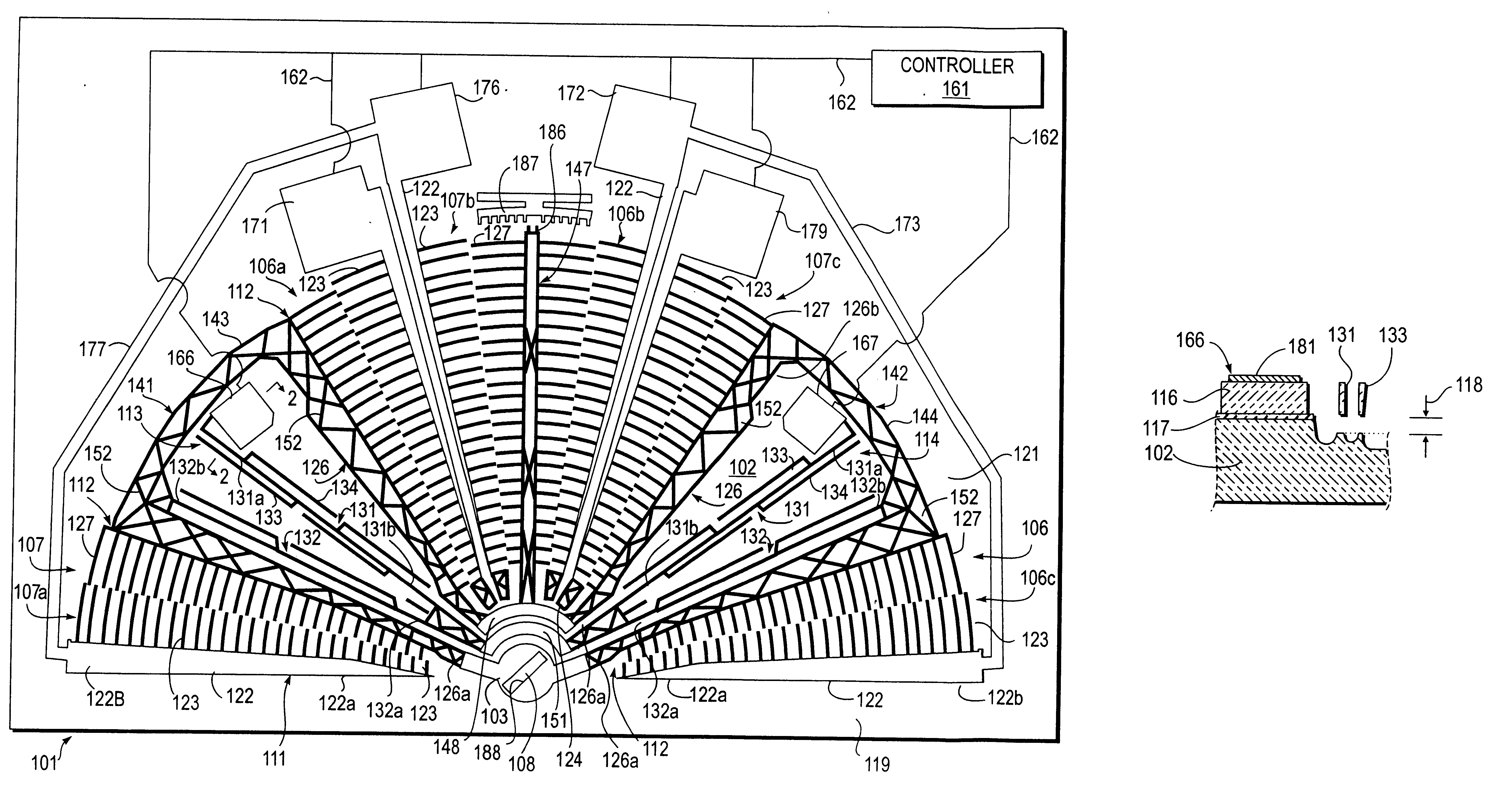
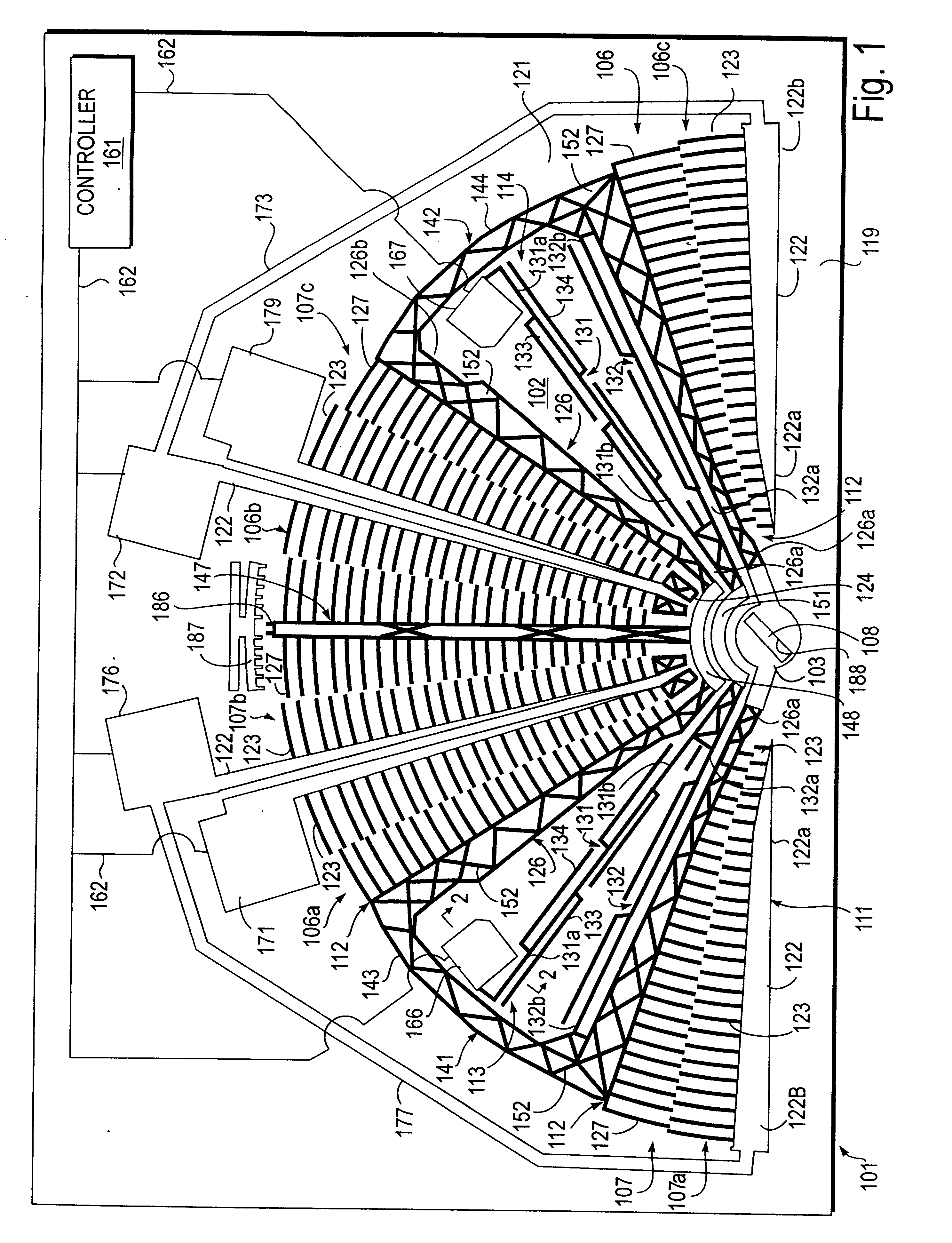
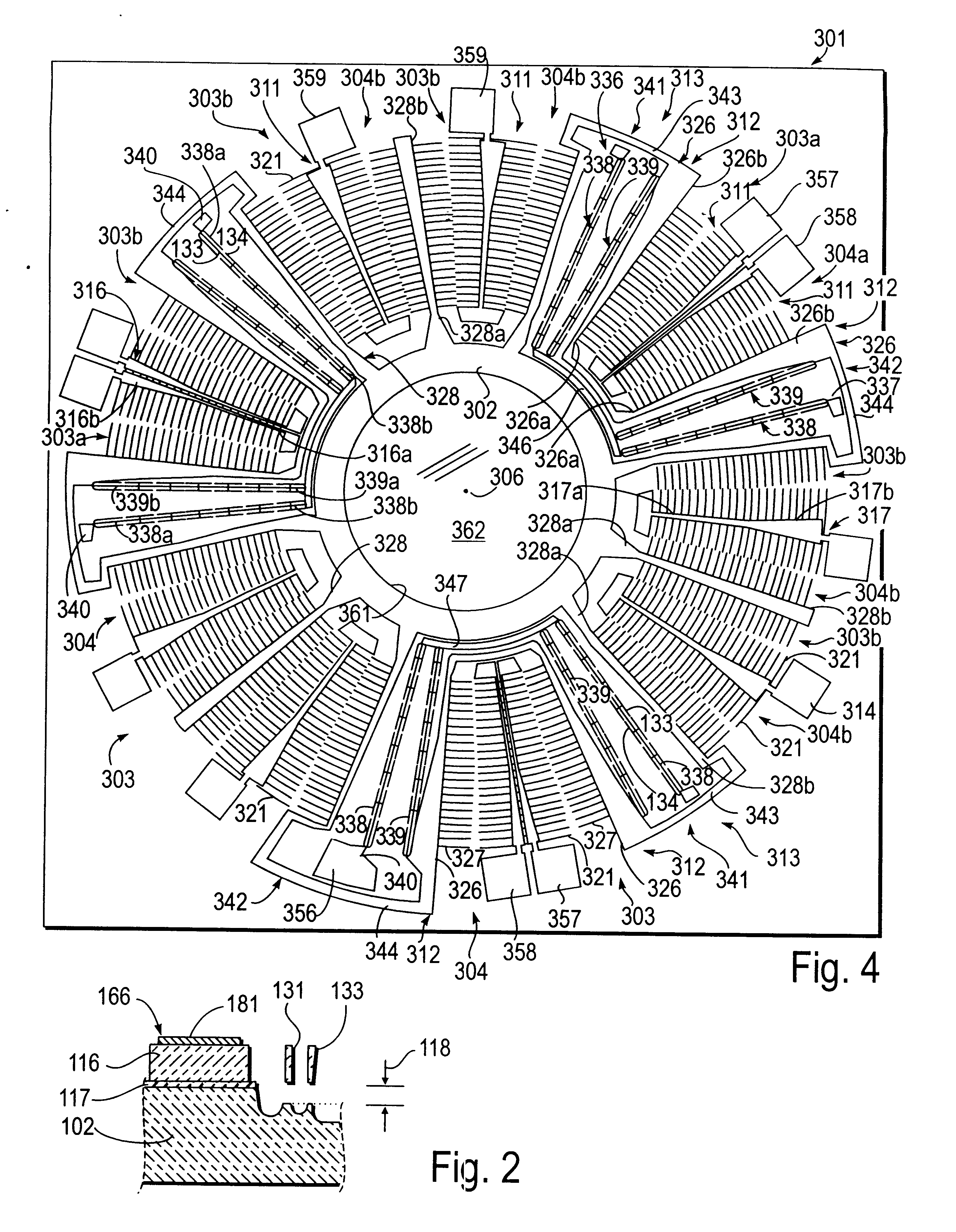
Rotary electrostatic microactuator 101 of the present invention is formed on a planar substrate 102 (see FIGS. 1 and 2). A rotatable member or circular mirror holder 103 overlies the substrate 102. A plurality of first and second comb drive assemblies 106 and 107 are carried by substrate 102 for rotating mirror holder 103 in first and second opposite angular directions about an axis of rotation 108 extending through the center of the circular mirror holder 103 perpendicular to planar substrate 102 and thus FIG. 1. Each of the first and second comb drive assemblies 106 and 107 includes a first comb drive member or comb drive 111 mounted on substrate 102 and a second comb drive member or comb drive 112 overlying the substrate 102. First and second spaced-apart springs 113 and 114 are included in microactuator 101 for supporting or suspending second comb drives 112 and mirror holder 103 above the substrate 102 and for providing radial stiffness to the movable second comb drives 112 and...


PUM

PropertyMeasurementUnit
thicknessaaaaaaaaaa
thicknessaaaaaaaaaa
thicknessaaaaaaaaaa

Abstract

A rotary electrostatic microactuator that includes a substantially planar substrate and a rotatable member overlying the substrate for rotation about an axis of rotation extending perpendicular to the planar substrate. First and second spaced-apart springs and a plurality of comb drive assemblies are included. Each of the comb drive assemblies has a first comb drive member mounted on the substrate and a second comb drive member. Each of the first and second comb drive members are provided with arcuate comb drive fingers. Each of the first and second springs has a first end portion secured to the substrate and a second end portion secured to at least one of the second comb drive members for suspending the second comb drive members and the rotatable member over the substrate. The second comb drive members are movable in a direction of travel about the axis of rotation between a first position in which the comb drive fingers of the first and second comb drive members are not substantially fully interdigitated and a second position in which the comb drive fingers of the first and second comb drive members are substantially fully interdigitated.

Description

SCOPE OF THE INVENTIONThe present invention relates generally to electrostatic actuators and more particularly to rotary electrostatic microactuators with comb drive assemblies.Many early rotating electrostatic motors used a central bearing with various arrangements of electrostatic stators around the motors to effect rotation. Unfortunately, these motors tended to have problems with friction at the central bearing and have had lifetime issues related to wear of the bearing. The motors typically acted as stepper motors where the rotor rotates with an incremental motion as the stator elements are attracted. Thus it was difficult to precisely adjust a plate to a particular angle with such motors.Other angular motors have been described which use flexural elements to support a rotating element. Comb drive fingers are arranged in concentric arcs around a central flexural pivot, so that small angular motion is provided around the pivot. See, for example, D. A. Horsley, et al., "Angular M...

Claims


Application Information

Patent Timeline
Patent Type & Authority Patents(United States)
IPC IPC(8): G02B6/35H02N1/00G11B11/00G11B11/105G11B7/085
CPCG02B6/3512G02B6/357H02N1/008G02B6/3548G02B6/3556G02B6/3584G11B7/08564G11B11/10563
Inventor JERMAN, JOHN H.GRADE, JOHN D.
Owner COHERENT INC
Why Eureka
Try Eureka