
Method and apparatus for controlling the drop volume in a selective deposition modeling environment

a technology of selective deposition and drop volume, applied in the direction of coatings, manufacturing tools, instruments, etc., can solve the problems of hampered layer unite ability and long wait time of the dispenser

Inactive Publication Date: 2002-02-12
3D SYST INC
View PDF13 Cites 87 Cited by
  • Summary
  • Abstract
  • Description
  • Claims
  • Application Information

AI Technical Summary

Problems solved by technology

For layers with large volumes, the dispenser may have to wait a long time until the previous layer freezes.
With regard to welding, sometimes the ability to unite layers is hampered when the volume of one layer is significantly larger (or smaller) than the volume of the other layers.

Method used


Image

  • Method and apparatus for controlling the drop volume in a selective deposition modeling environment
  • Method and apparatus for controlling the drop volume in a selective deposition modeling environment
  • Method and apparatus for controlling the drop volume in a selective deposition modeling environment

Examples


first embodiment

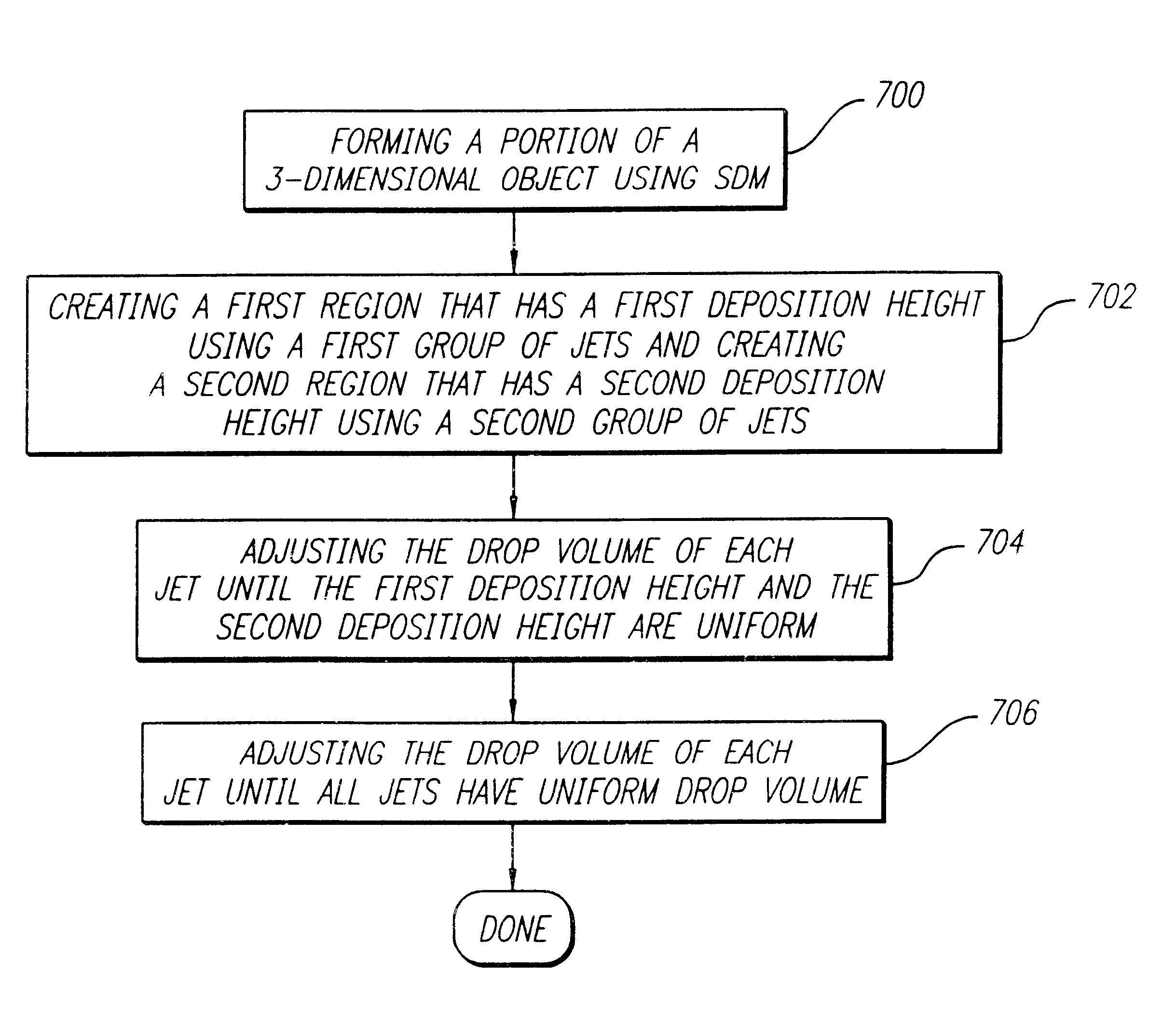
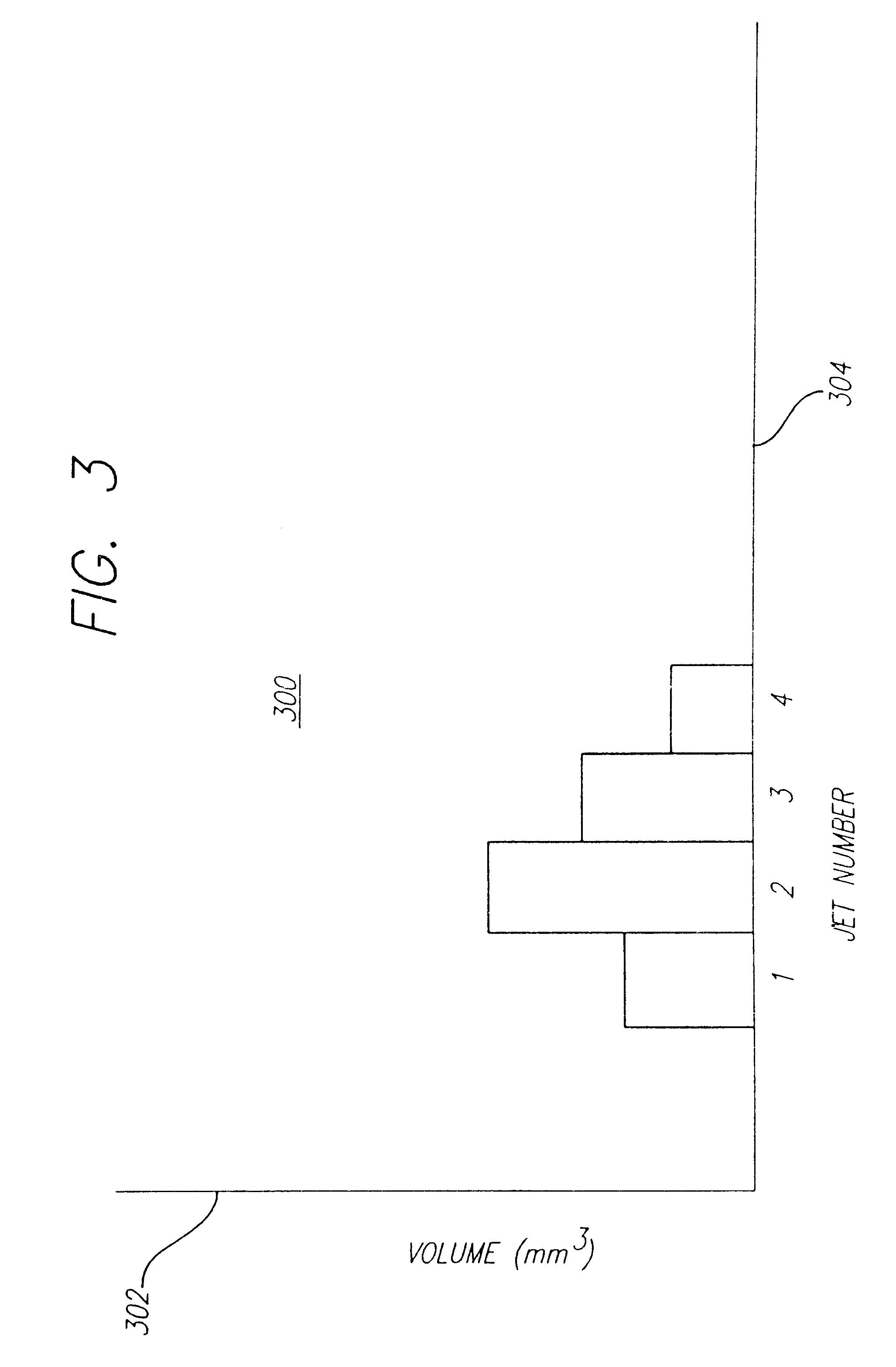
A second preferred embodiment is similar to the first embodiment with the exception that the drop volume capability of each jet is adjusted until the droplets of solidifiable material have uniform deposition heights. Specifically, each jet is adjusted until at least two regions with different deposition patterns have uniform deposition heights.

Since the layers comprise droplets, the deposition height of the droplets is related to the top (or bottom) surfaces of the layer. In particular, a layer that comprises droplets with varying deposition heights may have an uneven top (or bottom) surface. On the other hand, a layer that comprises droplets with uniform deposition heights may have a even top (or bottom) surface. The even surface can reduce the time required to build a three-dimensional object because the layers are thicker. The deposition height may be uniform within one layer or the deposition height may be uniform amongst all layers. In alternative configurations of the first em...

second embodiment

The third preferred embodiment is a combination of the first and second embodiment with the exception that a first group of jets produces the first region and a second group of jets produces the second region. As discussed herein, a group of jets is defined as a plurality of jets that are arranged at a closer spacing to each other than to any jet in any adjacent group. FIG. 6 displays exemplary groups of jets. Spacing between Jet group one 602 and Jet group two 604 is exaggerated for simplifying the present disclosure. Jet group one 602 and Jet group two 604 each have four jets 606 that are arranged with close spacing 608. As shown, a larger spacing 610 exists between the jets in jet group one 602 and the jets in jet group two 604.

The spacing between the raster lines 612 covered by the jets 606 is related to how the jets 606 are arranged. For example, a large raster line space 614 exists between jets in Jet group one 602 and jets in Jet group two 604. A small raster line space 616 e...


PUM

PropertyMeasurementUnit
Fractionaaaaaaaaaa
Fractionaaaaaaaaaa
Fractionaaaaaaaaaa

Abstract

A method, system and apparatus for forming a three-dimensional object on a layer-by-layer basis involves forming a portion of the three-dimensional object using selective deposition modeling (SDM). SDM involves using at least one orifice, such as a jet, which dispenses a droplet of a flowable material that solidifies upon being dispensed. A drop volume capability of each orifice is adjusted until substantially all orifices have a uniform drop volume capability and all dispensed droplets of the flowable material have a uniform volume.

Description

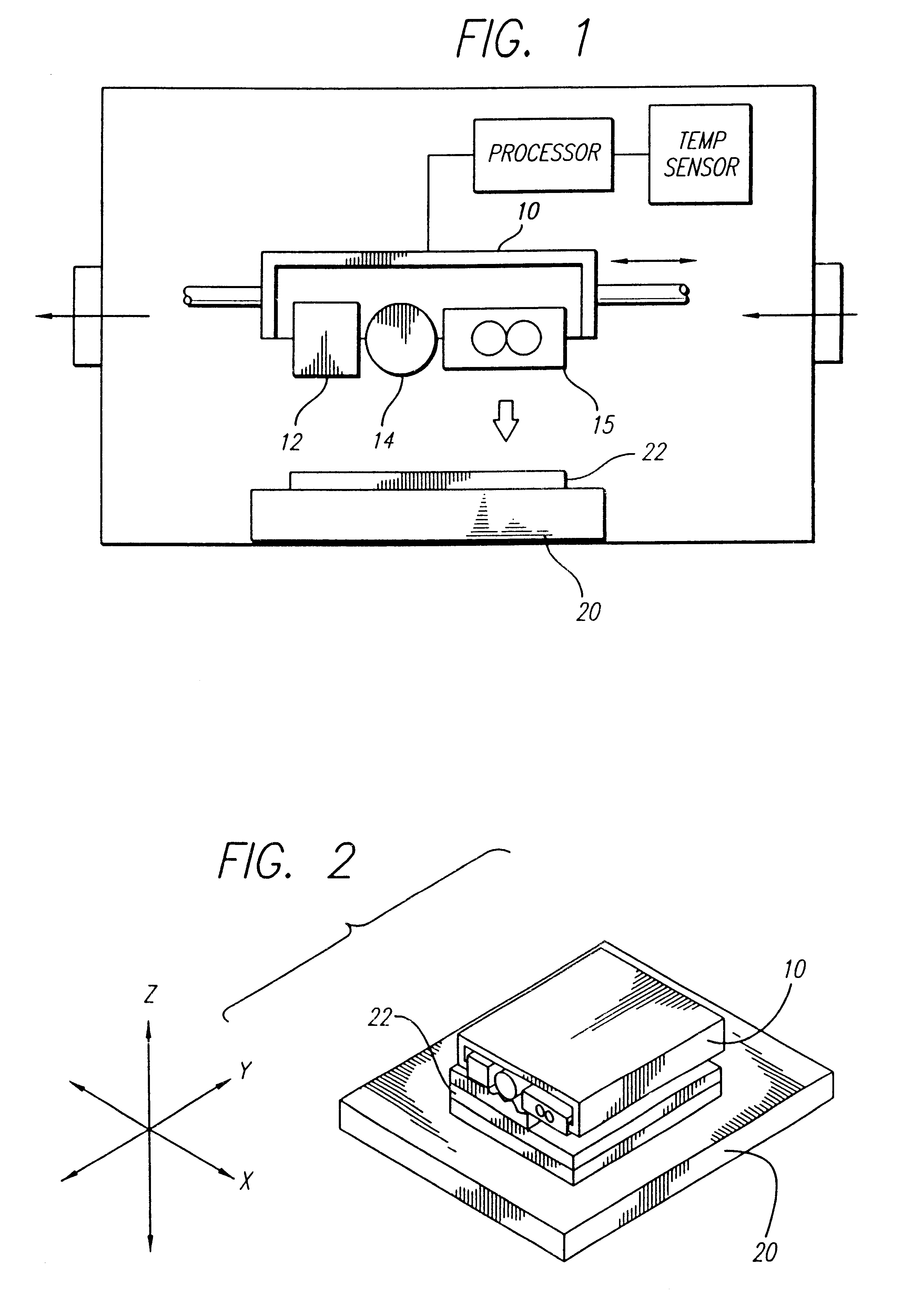
This invention relates to the formation of three-dimensional objects on substantially a layer-by-layer basis with enhanced resolution. Preferred embodiments of the invention more particularly relate to controlling the drop volume in a selective deposition modeling environment.Related ArtRapid Prototypying and Manufacturing (RP&M) is the name given to a field of technologies that can be used to form three-dimensional objects rapidly and automatically from three-dimensional computer data representing the objects. RP&M can be considered to include three classes of technologies: (1) Stereolithography; (2) Laminated Object Manufacturing; and (3) Selective Deposition Modeling.The stereolithography class of technologies creates three-dimensional objects based on the successive formation of layers of a fluid-like medium adjacent to previously formed layers of medium and the selective solidification of those layers according to cross-sectional data representing successive slices of the three...

Claims


Application Information

Patent Timeline
IPC IPC(8): B29C41/12B29C41/34B29C41/36B29C67/00G06T17/00
CPCB29C41/12B29C41/36G06T17/00B29C67/0092B29C67/0059B29C64/112B29C64/40B33Y10/00B33Y30/00B33Y40/00
Inventor BEDAL, BRYAN J. L.BUI, LOC V.
Owner 3D SYST INC
Learn More