
Multiple-parameter control of lamp ignition

Inactive Publication Date: 2002-03-19
PHILIPS ELECTRONICS NORTH AMERICA
View PDF10 Cites 3 Cited by
  • Summary
  • Abstract
  • Description
  • Claims
  • Application Information

AI Technical Summary

Benefits of technology

Igniting of a gaseous discharge lamp in accordance with the invention provides a means for preventing the continued application of igniting power to non-functional or missing lamps and also for inhibiting "cycling" of end-of-life lamps. In either case, the detected lamp voltage will remain above the upper threshold voltage while igniting pulses are applied for longer than the predetermined time period. This is achieved by adjusting the upper threshold voltage and the predetermined time period to values that correspond to an age which is deemed to be a lamp's useful end-of-life. Further, by enabling the application of igniting pulses even while the lamp voltage is below the lower threshold voltage, the continued generation of such pulses will be permitted if a lamp that has not warmed up falls out of ignition.
In accordance with another feature of the invention, a timer for measuring the elapsed time is reset whenever the lamp voltage decreases from a voltage above the upper threshold voltage to a voltage below the upper threshold voltage. This ensures that the timer will allow the full predetermined time period to elapse if power is subsequently interrupted, regardless of the brevity of the interruption.

Problems solved by technology

Such circuit arrangements continually reignite (or attempt to reignite) lamps which are near their end of life.
This undesirable trait, commonly called "cycling", both stresses the circuitry and lessens the likelihood of timely detecting and replacing end-of-life lamps.
This is a common problem with certain types of gaseous-discharge lamps, such as high-pressure sodium (HPS) lamps, which have operating voltages that increase substantially with age.
If power to an operating lamp is momentarily interrupted, the interruption may be long enough to extinguish the lamp but too short to enable reset of the timer.
In this situation, the timer will not run at all or will provide less than the predetermined time needed to re-ignite the lamp.

Method used


Image

  • Multiple-parameter control of lamp ignition
  • Multiple-parameter control of lamp ignition
  • Multiple-parameter control of lamp ignition

Examples


Embodiment Construction

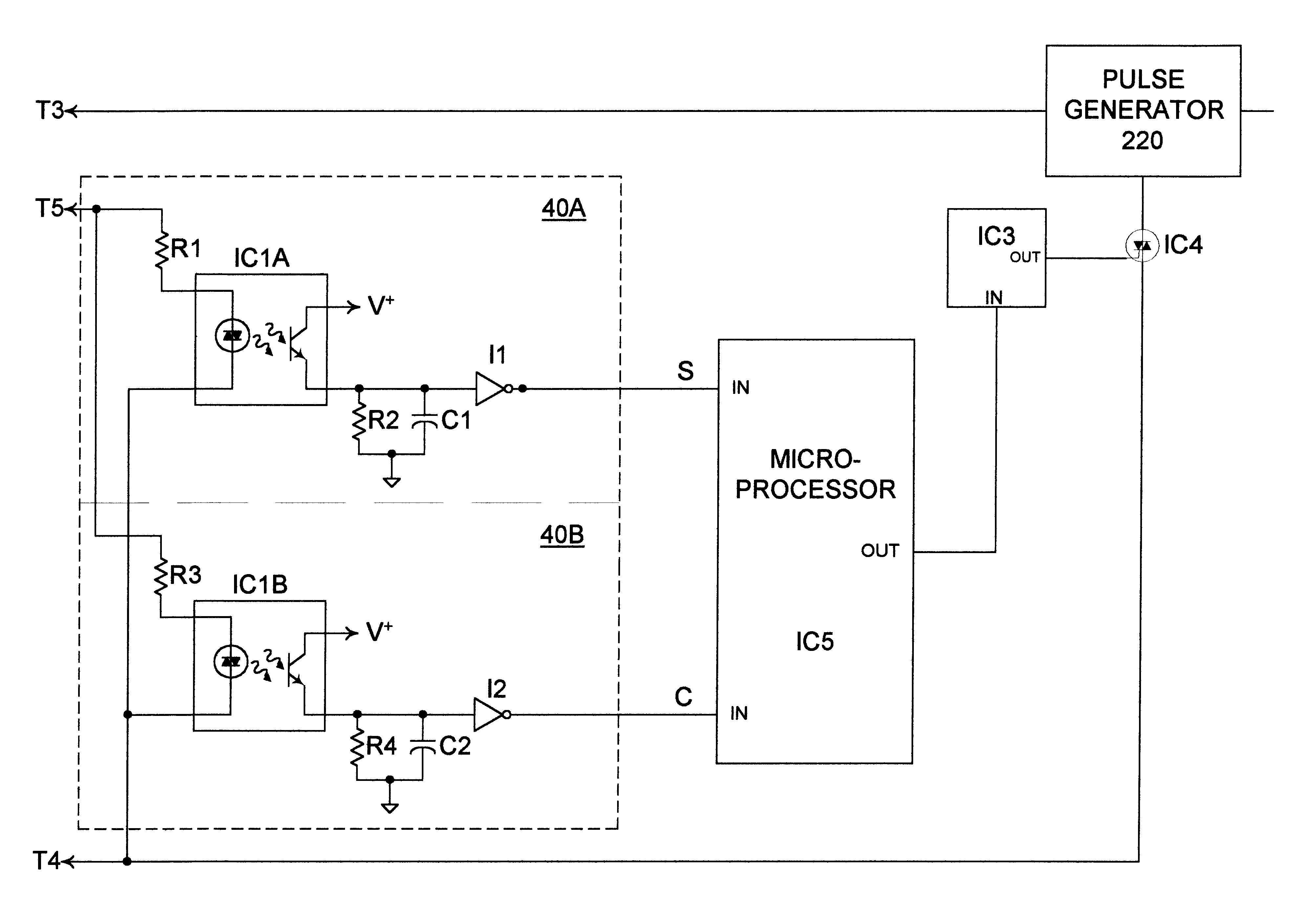
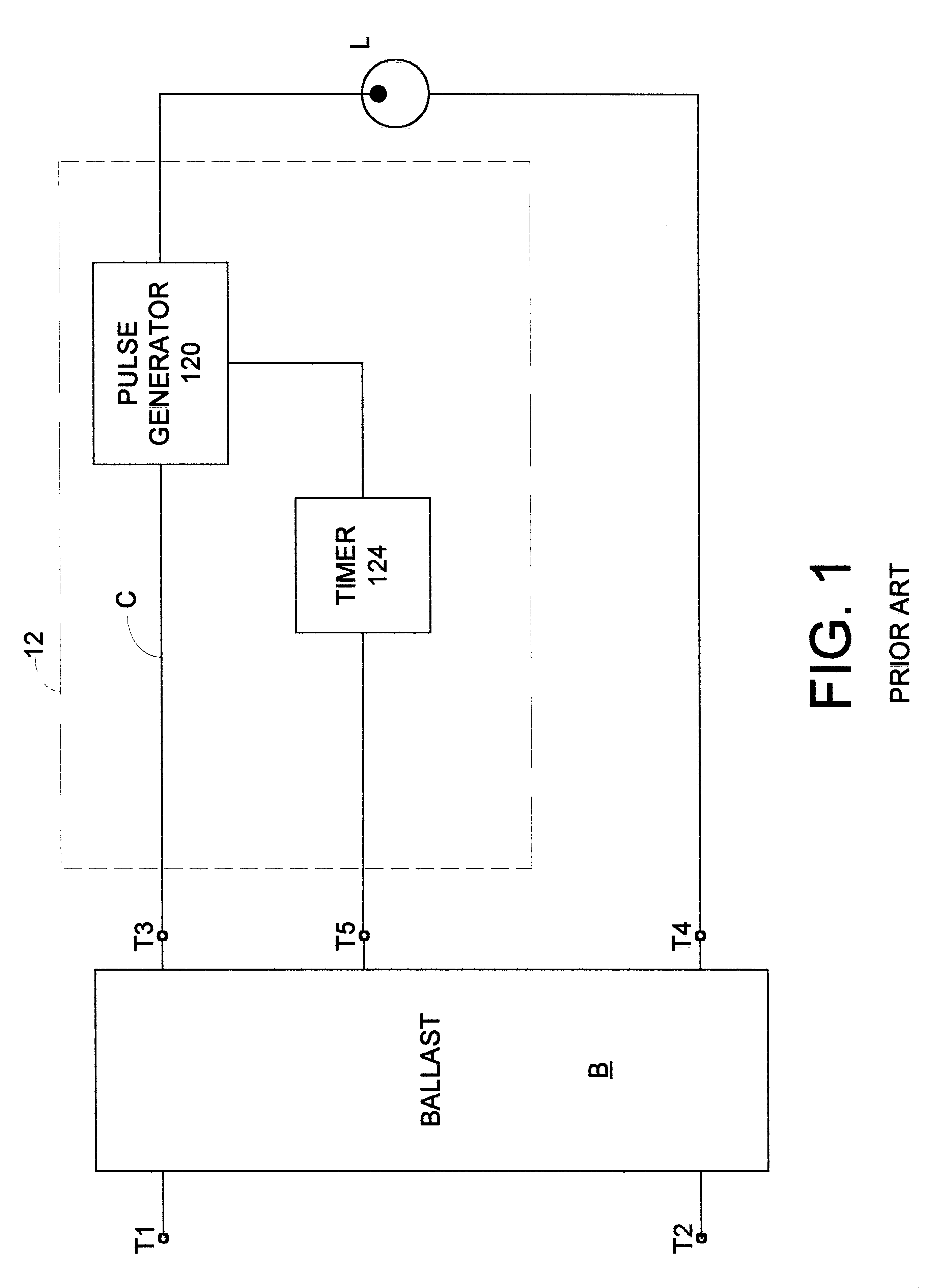
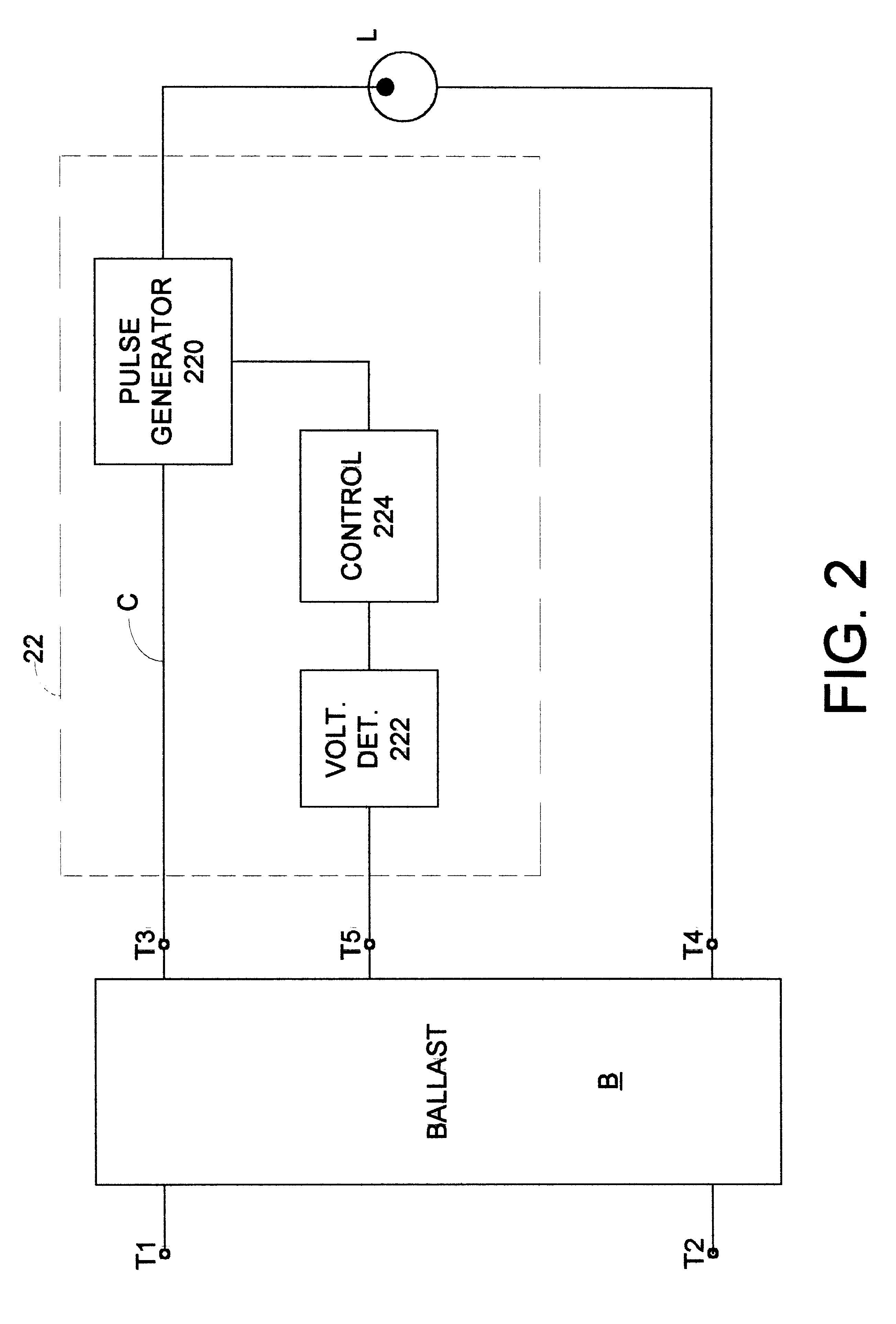
FIG. 2 illustrates a preferred embodiment of a circuit arrangement for igniting and powering a gaseous discharge lamp in accordance with the invention. Similarly to FIG. 1, the circuit arrangement includes a ballast B for powering a gaseous discharge lamp L, which is electrically connected to terminals T3 and T4, when a source of AC voltage is connected to terminals T1 and T2. Also as in FIG. 1, the circuit arrangement has an ignitor 22 including a pulse generator 220 for applying high-voltage pulses to the lamp L to effect ignition. Any ballast B and pulse generator 220, which are adapted for igniting and powering the specific gaseous discharge lamp L, may be employed In addition to the pulse generator 220, the ignitor 22 includes a voltage detector 222 and control circuitry 224 for controlling ignition and operation of the lamp L by utilizing a plurality of known operating characteristics of the lamp. These include voltage characteristics and time-period characteristics.

FIG. 3A il...


PUM


Abstract

Starting of a gaseous discharge lamp is control led in response to both lamp voltage and duration of time during which igniting pulses are applied. An upper and a lower threshold voltage are utilized to determine whether the lamp is in an unstable starting mode, a cold starting mode, or a steady-state operating mode.

Description

1. Field of the InventionThis invention relates to gaseous discharge lamps which ignite at voltages that are much higher than their operating voltages and, in particular, to the igniting of such lamps.2. Description of Related ArtCommon characteristics of a gaseous discharge lamp are its negative resistance and high igniting voltage. A circuit arrangement for powering such a lamp typically includes a current limiting means, such as a ballast, to compensate for the negative resistance, and often includes circuitry for generating high-voltage pulses to ignite the lamps. Such pulse-generator circuitry typically includes a voltage-sensitive switch (e.g. a sidac) for effecting the continual production of the high-voltage pulses until the lamp ignites. Upon ignition, the voltage across the lamp decreases from a higher open-circuit voltage (OCV) to a lower voltage, which causes the switch to change to a non-conducting state and to effect termination of pulse production. Such a circuit arra...

Claims


Application Information

Patent Timeline
IPC IPC(8): H05B41/28H05B41/04H05B41/292H05B41/00H05B41/18
CPCH05B41/2925H05B41/042
Inventor WICKLUND, KURT W.TROY, PATRICK E.
Owner PHILIPS ELECTRONICS NORTH AMERICA
Learn More