Lighting apparatus for discharge lamp

a technology of discharge lamp and discharge lamp, which is applied in the direction of electric variable regulation, process and machine control, instruments, etc., can solve the problems of increasing the amount of generated heat, large loss, and increasing the power loss of the lighting circuit, so as to prevent the continued application of excessive transient power

Inactive Publication Date: 2008-02-19
KOITO MFG CO LTD
View PDF10 Cites 6 Cited by
  • Summary
  • Abstract
  • Description
  • Claims
  • Application Information

AI Technical Summary

Benefits of technology

[0013]It is therefore an object of the invention to take measures to circuit protection by reducing maximum applied power (allowable upper limit value) over time in a discharge lamp lighting apparatus for preventing continued application of excessive transient power to the lighting apparatus in the event of a failure in a load. However, exemplary embodiments of the present invention are not required to achieve this object or any other objects, and may also achieve objects other than this object.
[0014]The invention provides a lighting apparatus for a discharge lamp which is configured to reduce power applied to the discharge lamp over time after it is applied with initial maximum power exceeding the rated power in a transient period from the time the discharge lamp is lit from a cold state to the time the discharge lamp reaches a static lighting state. The lighting apparatus includes a maximum power regulator circuit for regulating the applied power in the transient period such that the applied power does not exceed an upper limit power line which is reduced over time after the application of the initial maximum power.
[0016]Thus, in the transient power control, the invention can prevent the application of excessive transient power from continuing for a time more than necessary in the event of a failure in a load, thus limiting the amount of generated heat and preventing thermal destruction and the like.
[0017]The invention can take sufficient circuit protection measures by preventing thermal detrimental effects resulting from the continuous application of transient power to the discharge lamp.
[0018]The lighting apparatus may further comprise a DC-DC converter circuit for converting a received DC input voltage to a desired DC voltage, and a control circuit for controlling the power applied to the discharge lamp. The control circuit may include an error processing unit, and a control signal generator responsive to a signal from the error processing unit for generating a control signal which is sent to the DC-DC converter circuit. The error processing unit receives a reference signal at one input, and an output signal of the maximum power regulator circuit multiplexed on a power control signal, which is calculated based on information on a detected voltage or current associated with the discharge lamp, at the other input. With the foregoing configuration, the lighting apparatus of the invention can reduce the allowable upper limit value for the power applied to the discharge lamp over time without involving a complicated control scheme, a significant increase in cost, and the like.

Problems solved by technology

Power loss of a lighting circuit increases as larger power is outputted.
When large power is applied to a lamp, as with the cold start, a large loss occurs, which increases the amount of generated heat.
For example, in the event of a leak or submergence of a bulb, troubles caused by manufacturing-related faults and aging deterioration (an excessively small amount of mercury, a reduction in inner pressure of an arc tube, and the like), a failure in a lamp, and the like, or when an accident brings about an equivalence to a parallel circuit of a lamp and a low resistor in a lamp connector, a lamp voltage detected by a detector circuit included in a lighting circuit indefinitely remains low, possibly resulting in continuous application of excessive power to the lamp.
However, the related art techniques have problems of insufficient measures for protecting circuits from heat generated by a failed load, an increased cost therefor, and the like.
For example, when a high-frequency switching scheme is employed to reduce the size of a lighting apparatus having a fly-back type DC-DC converter circuit, continued application of excessive power, in the event of a failure, can directly lead to thermal runaway, thermal destruction, and the like, due to a reduced thermal capacitance of the overall apparatus.

Method used


Image

  • Lighting apparatus for discharge lamp
  • Lighting apparatus for discharge lamp
  • Lighting apparatus for discharge lamp

Examples


Embodiment Construction

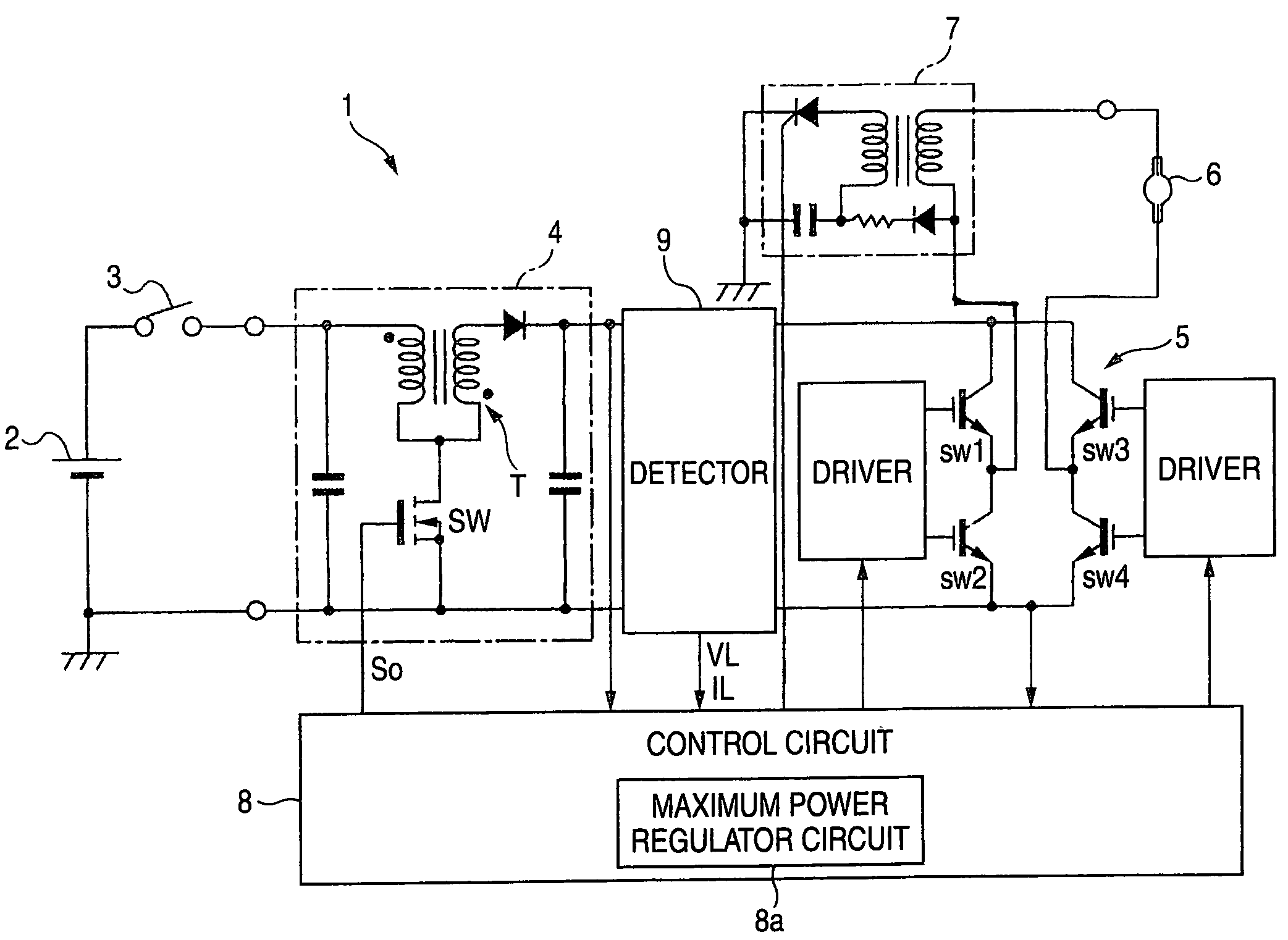
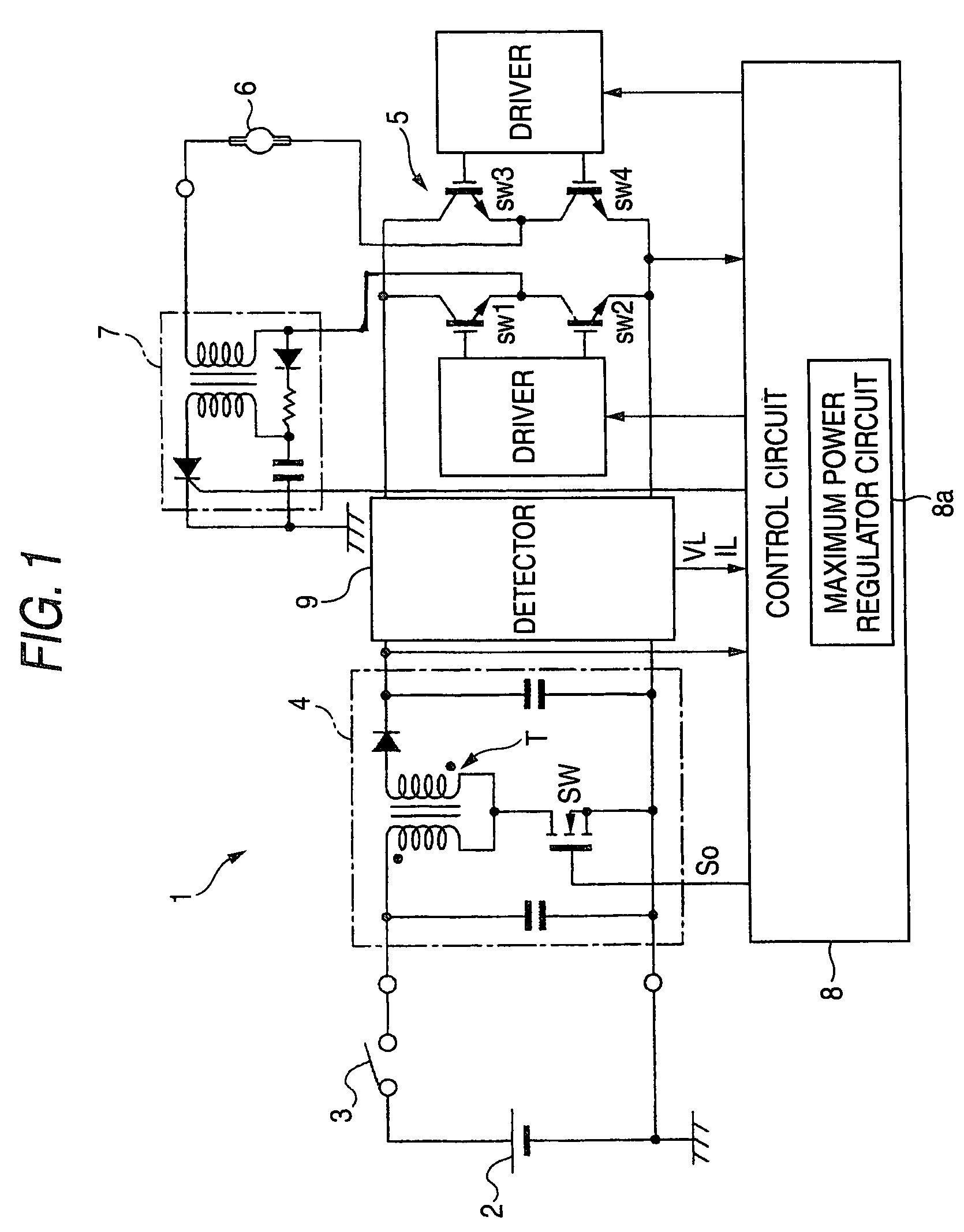
[0025]FIG. 1 illustrates an exemplary, non-limiting basic configuration of a discharge lamp lighting apparatus 1.

[0026]DC voltage from a DC power supply 2 is supplied to a DC-DC converter circuit 4 through a noise filter circuit, not shown, by turning on a lighting switch 3.

[0027]The DC-DC converter circuit 4 receives a DC input voltage from the DC power supply 2, and converts the received DC input voltage to a desired DC voltage. For example but not by way of limitation, a fly-back type DC-DC converter can be used for the DC-DC converter circuit 4. In a circuit configuration having a transformer T and a switching element SW on the primary side of the transformer T, the switching element SW is driven by a control signal So from a control circuit 8, later described.

[0028]A DC-AC converter circuit 5 is provided for converting an output voltage of the DC-DC converter circuit 4 to an AC voltage that is supplied to a discharge lamp 6. For example but not by way of limitation, in a circui...


PUM


Abstract

In a discharge lamp lighting apparatus, in a transient period from the time a discharge lamp is lit in a cold state to the time the discharge lamp reaches a static lighting state, the power applied to the discharge lamp is reduced over time after an initial maximum power that exceeds the rated power. A maximum power regulator circuit is provided to regulate the applied power in the transient period such that the applied power does not exceed an upper limit power line M1 or M2 that is reduced over time after the application of the initial maximum power. In this way, the application of excessive transient power is prevented from continuing longer than necessary in the event of a failure in a load, thus limiting the amount of generated heat and preventing thermal destruction.

Description

[0001]This application claims foreign priority based on Japanese application no. JP2004-227908, filed on Aug. 4, 2004, the contents of which is incorporated herein in its entirety. This priority claim is being made concurrently with the filing of this application.BACKGROUND[0002]1. Technical Field[0003]The present invention relates to techniques for preventing a discharge lamp from being continuously applied with excessive power more than necessary due to failure in a load when the discharge lamp is turned on from a cold state.[0004]2. Background Art[0005]When a discharge lamp is used for car illumination, light flux must be rapidly increased after the discharge lamp is turned on, so that a transient power control is conducted to supply larger power immediately after the discharge lamp is lit than the power applied for a normal lighting situation, and further, to reduce the applied power over time.[0006]For example, for a metal halide lamp with rated power of 35 W, when lighting is ...

Claims


Application Information

Patent Timeline
Patent Type & Authority Patents(United States)
IPC IPC(8): H05B37/02H05B41/285
CPCH05B41/2925Y02B20/208Y10S315/07H05B45/38Y02B20/00Y02B20/30H05B41/2855H05B41/2856H05B41/2926
Inventor ICHIKAWA, TOMOYUKI
Owner KOITO MFG CO LTD
Why Eureka
Try Eureka