

Antenna apparatus and portable radio set
a portable radio and antenna technology, applied in the direction of diversity/multi-antenna systems, resonant antennas, independent non-interacting antenna combinations, etc., can solve the problems of speech quality decline and performance degradation of cellular telephone 1
- Summary
- Abstract
- Description
- Claims
- Application Information
AI Technical Summary
Problems solved by technology
Method used
Image

Examples
first embodiment
(2) First Embodiment
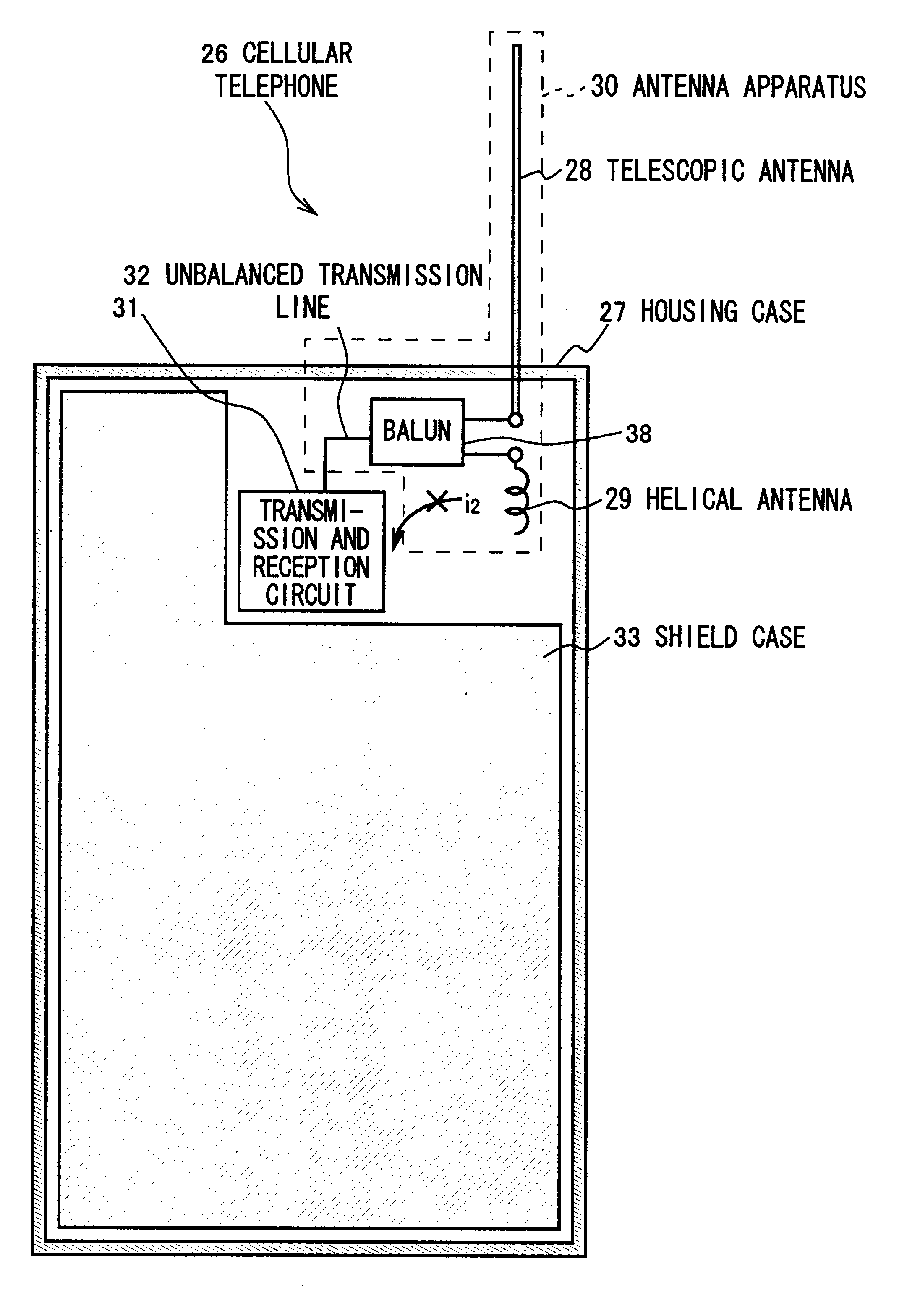
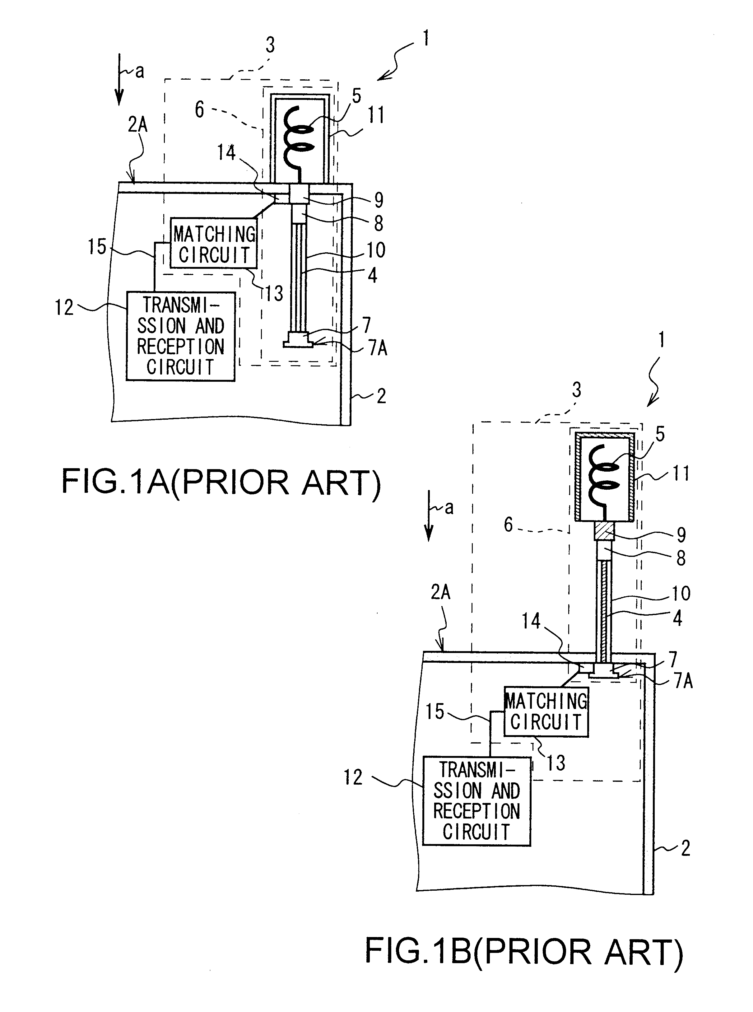
In FIG. 20, in which a same numeral is assigned to a part corresponding to the identical part of the FIG. 16, reference numeral 51 denotes the cellular telephone according to the first embodiment as a whole and configured by installing the antenna apparatus 52 in the housing case 27 made of the nonconductive material such as a synthetic resin.
The antenna apparatus 52 has the first antenna part 53, which is installed retractably and pullably along with the retracting direction and the reversal pulling direction shown by an arrow b almost parallel to the length direction (hereafter, housing length direction) of the housing case 27 in the back face 27B of the top end 27C of the housing case 27, and a fixed type second antenna part 54, which is located around the top end 27C of the inside of the housing case.
Here, FIGS. 21A and 21B are those showing the internal configuration of the cellular telephone 51, excepting a matching circuit and the shield case. In the first...
second embodiment
(3) Second Embodiment
FIGS. 22A and 22B, in which the same numeral is assigned to a part corresponding to the identical part of the FIGS. 21A and 21B, show the cellular telephone 65 according to the second embodiment, and configuration thereof is same as that of the cellular telephone 51 (FIGS. 21A and 21B) according to the first embodiment as described above excluding the configuration of the first antenna part 67 of the antenna apparatus 66 and the position in which the second antenna part 54 is arranged.
In the second antenna part 54, the second central axis of the second helical antenna is made almost parallel to the first central axis of the first helical antenna 56, and in retracting the first antenna part 67, the second helical antenna 62 is located in a predetermined position in a distance from the telescopic antenna 55 to inhibit capacitive coupling inside the housing case 27.
Consequently, in the antenna apparatus 66, in retracting the first antenna part 67, it is pushed in t...
third embodiment
(4) Third Embodiment
FIGS. 23A and 23B, in which a same numeral is assigned to the part corresponding to the identical part of the FIGS. 22A and 22B, show the cellular telephone 69 according to the third embodiment, and is configured similar to the cellular telephone 65 (FIGS. 23A and 23B) according to the second embodiment as described above excluding the arranging attitude of the second antenna part 54 of the antenna apparatus 70.
Here, for example, in the antenna apparatus 52 (FIGS. 21A and 21B) and 66 (FIGS. 22A and 22B) according to the first and the second embodiments as described above, the telescopic antenna 55 is located making the telescopic length direction almost parallel to the housing length direction, and the first and second helical antennae 56 and 62 are located making the first and the second central axes almost parallel to the housing length direction. Therefore, when the telescopic antenna 55 and the second helical antenna 56 and the first and second helical antenn...
PUM
 Abstract
Description
Claims
Application Information