Plastic coil and method of forming same

a technology of plastic coils and coils, applied in the field of plastic coils, can solve the problems of plastic coil wires that cannot be wound around a spool for storage and carrying, important waste of plastic coil materials, and extra coil materials

Inactive Publication Date: 2002-04-02
2751 3654 QUEBEC
View PDF19 Cites 8 Cited by
  • Summary
  • Abstract
  • Description
  • Claims
  • Application Information

AI Technical Summary

Benefits of technology

It is the gist of the present invention to provide a plastic coil and a method for forming such plastic coils with a coil forming apparatus which improves on the existing methods, and more particularly which allows the output of the coil forming apparatus to feed a continuous, non-rotating plastic coil.

Problems solved by technology

The main problem associated with this conventional method for forming plastic coils is that the coil discharged by the helical channel is imparted with a rotative movement about its longitudinal axis, in addition to the desired output discharge translational movement along this same longitudinal axis.
Thus, the plastic coil wire cannot be wound around a spool for storing and carrying purposes, because of the coiled wire rotating on itself which would result in an undesirable twisting of the plastic coil on the spool.
Not only is it less interesting to sell the coils in short lenghts, but also to cut the plastic coil is likely to result in an important waste of plastic coil material.
Indeed, if the length at which the coil is cut (e.g. three feet) is not a multiple of the effective used lengths of the coils (e.g. to bind books having a length of two feet), then the extra coil material (e.g. one foot long for each three feet coil) must be discarded and is wasted.

Method used


Image

  • Plastic coil and method of forming same
  • Plastic coil and method of forming same
  • Plastic coil and method of forming same

Examples


Embodiment Construction

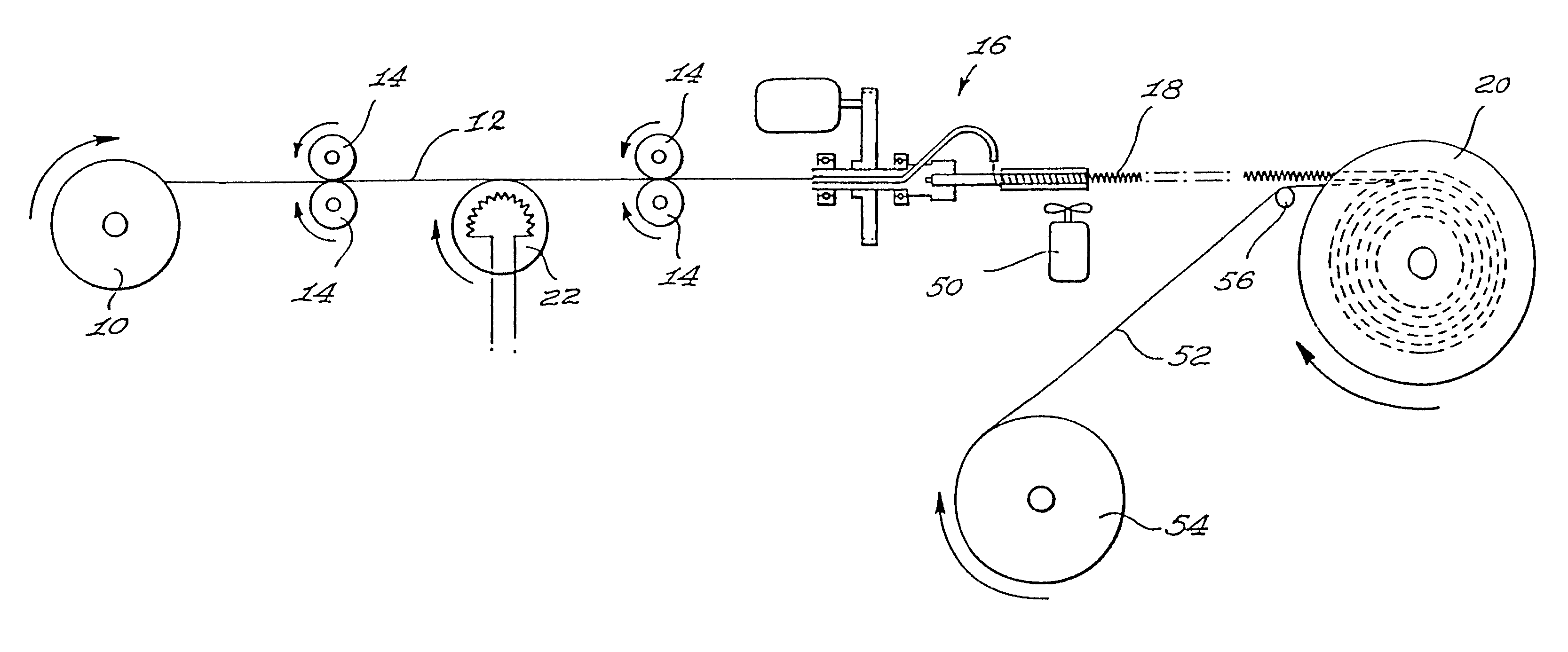
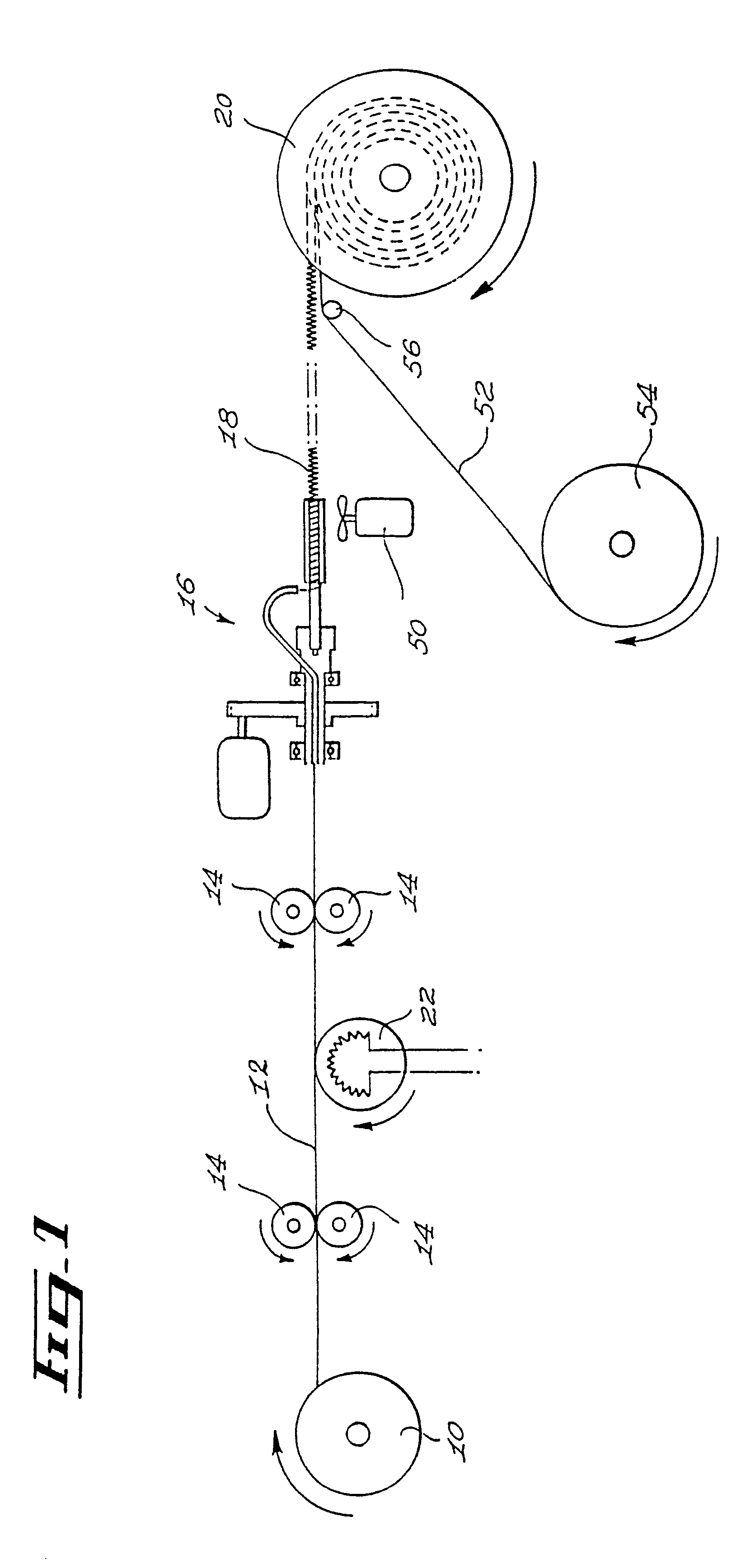
FIG. 1 schematically shows a wire supply spool 10 supplying a straight continuous flexible thermoplastic wire 12. Wire 12 is conveyed by means of a number of feeding rollers 14, e.g. four feeding rollers 14, into a plastic coil forming apparatus 16 according to the invention. Apparatus 16 forms an elongated continuous plastic coil 18 from wire 12, and preferably comprises a storing spool 20 for wounding and storing coil 16 in a manner which will be detailed hereinafter. A conventional heater device 22 is provided adjacent wire 12 and is located upstream of the rest of apparatus 16, for example between two successive pairs of feeding rollers 14, so that wire 12 may achieve a semi-viscous state which is characterized by the fact that it becomes soft and pliable while maintaining a sufficient intrinsic structural integrity to be propelled by the feeding rollers 14 throughout apparatus 16. Power means (not shown) drive rollers 14 into their rotative movement at a selected speed.
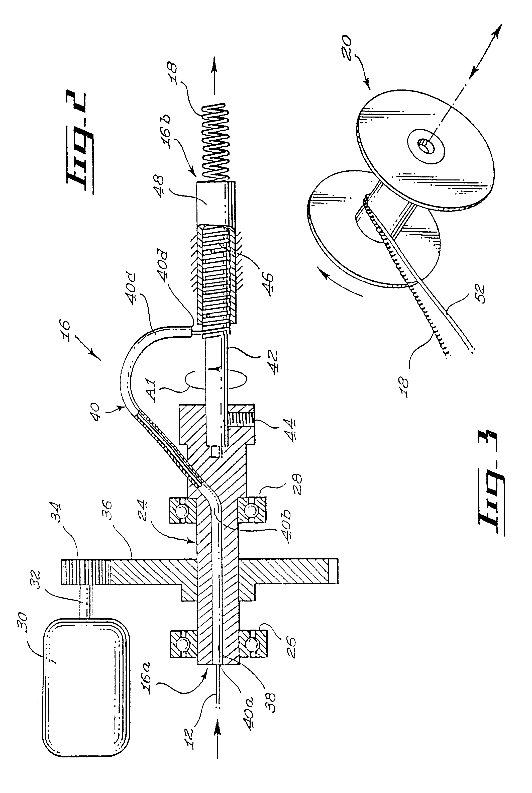
FIG. 2 s...


PUM

PropertyMeasurementUnit
lengthsaaaaaaaaaa
lengthaaaaaaaaaa
lengthaaaaaaaaaa

Abstract

A continuous thermoplastic wire is heated and fed into a coil forming apparatus having a rotative drum holding an injection nozzle so that it registers with and be linked in a common rotative movement to a threaded mandrel also supported by the drum. The wire discharged by the nozzle slidably engages the threads of the mandrel into a helical pattern, the mandrel being radially and coaxially surrounded by a cooled sleeve. The wire will thus solidify along the helical thread of the mandrel, to form a continuous plastic coil being discharged at the downstream extremity of the mandrel and sleeve assembly. Due to the fact that the drum, mandrel and nozzle all rotate in a common rotative movement, it is possible to select the direction and speed of rotation of the three last-mentioned elements so that the coil being discharged have an ouput discharge translational speed, while being exempt of any absolute rotational movement about its longitudinal axis.

Description

The present invention relates to plastic coils, and more particularly to a method for forming these plastic coils.Plastic coils are well known through their several uses, for example to hingedly bind the pages of a book or booklet. The coils used this way are semi-rigid plastic wires forming a cylindroid helix of constant diameter and pitch. A particular advantage of this form of plastic coil binding element is that it is not expensive to produce, while being sturdy, offering a good aesthetic appearance and allowing an efficient and easy-to-use binding element for the book pages bound in this way.A known method of producing plastic coils comprises using a conveyor line for a thermoplastic wire in which the wire is heated so as to achieve a semi-viscous pliable state, and then fed into a helical channel in which its selected helical form is achieved by cooling the channel so that the thermoplastic wire will solidify and recover its semi-rigidity in the form of a coil shaped according...

Claims


Application Information

Patent Timeline
Patent Type & Authority Patents(United States)
IPC IPC(8): B29C53/32B29C53/00B65H55/00
CPCB29C53/12B29C53/32B65H55/00Y10T428/139B65H2701/3916Y10S428/906B65H2701/391
Inventor PRIMEAU, ANDRECORRIVEAU, REGENTBEDARD, JEAN T.BRISSON, JEAN-CLAUDE
Owner 2751 3654 QUEBEC
Why Eureka
Try Eureka