Lock and lock releasing mechanism in IC card connecting mechanism

a technology of ic card and ejector, which is applied in the direction of coupling device connection, coupling/disengagement part engagement, instruments, etc., can solve the problems of overly large ejector force of the card ejector, overly large load on the ic card, and even increased inconvenien

Inactive Publication Date: 2002-06-04
YAMAICHI ELECTRONICS
View PDF13 Cites 69 Cited by
  • Summary
  • Abstract
  • Description
  • Claims
  • Application Information

AI Technical Summary

Problems solved by technology

Because of the arrangement mentioned above, the pressing force of the card ejecting member tends to be overly large.
As a result, an overly large load is applied to the IC card due to the structure in which the lock member is pushed out of the recess by the IC card.
Those inconveniences are even increased when it is attempted to enlarge the card retaining force by increasing the resilient force of the lock member.
However, this heart cam mechanism inherently involves such problems that the structure is complicated and machining of high degree of accuracy is required.
In addition, it has such problems that since the cam is slidingly moved through a complicated locus, the cam is susceptible to wear and in some instances, the heart cam fails to guide properly which often results in malfunction.

Method used


Image

  • Lock and lock releasing mechanism in IC card connecting mechanism
  • Lock and lock releasing mechanism in IC card connecting mechanism
  • Lock and lock releasing mechanism in IC card connecting mechanism

Examples


Embodiment Construction

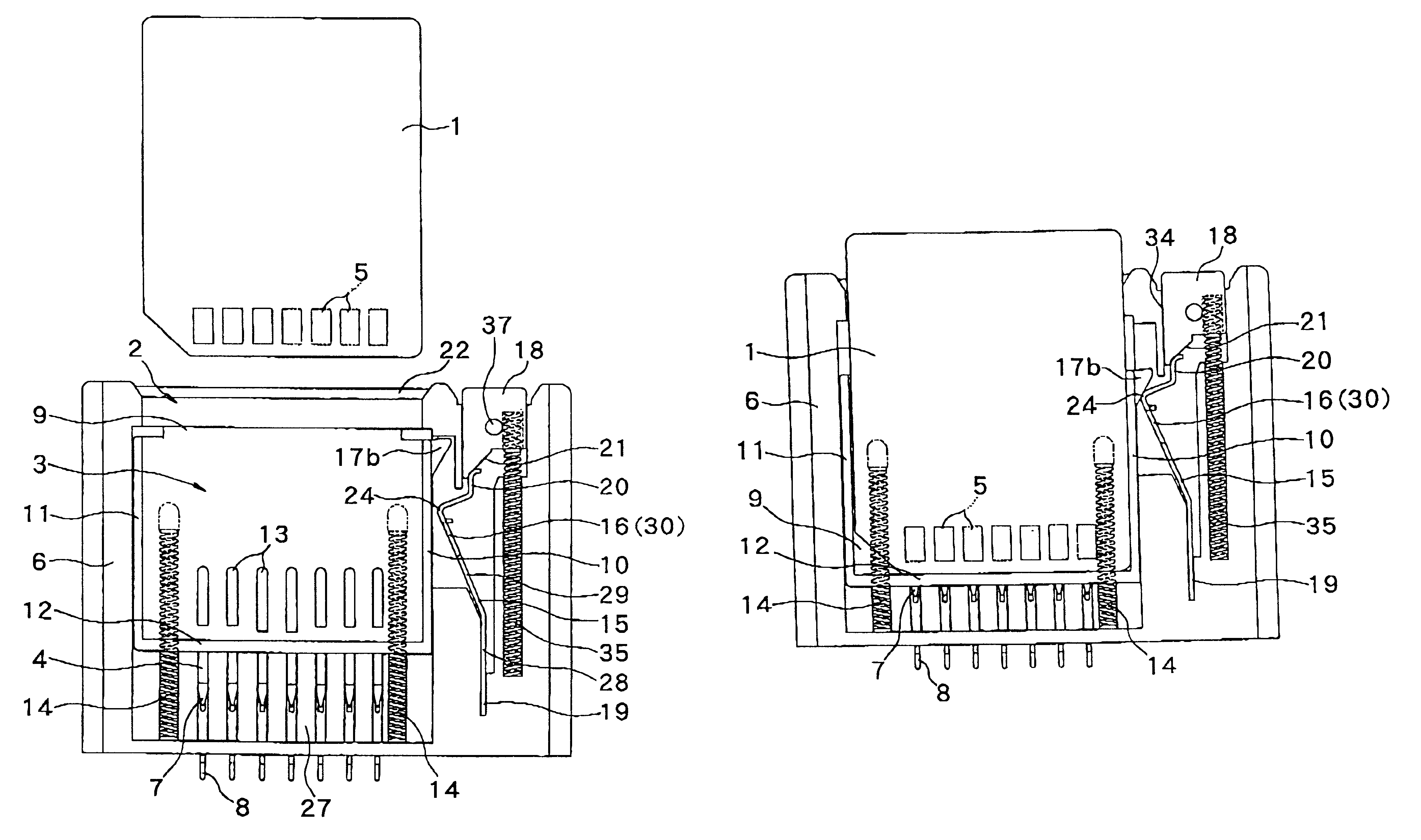
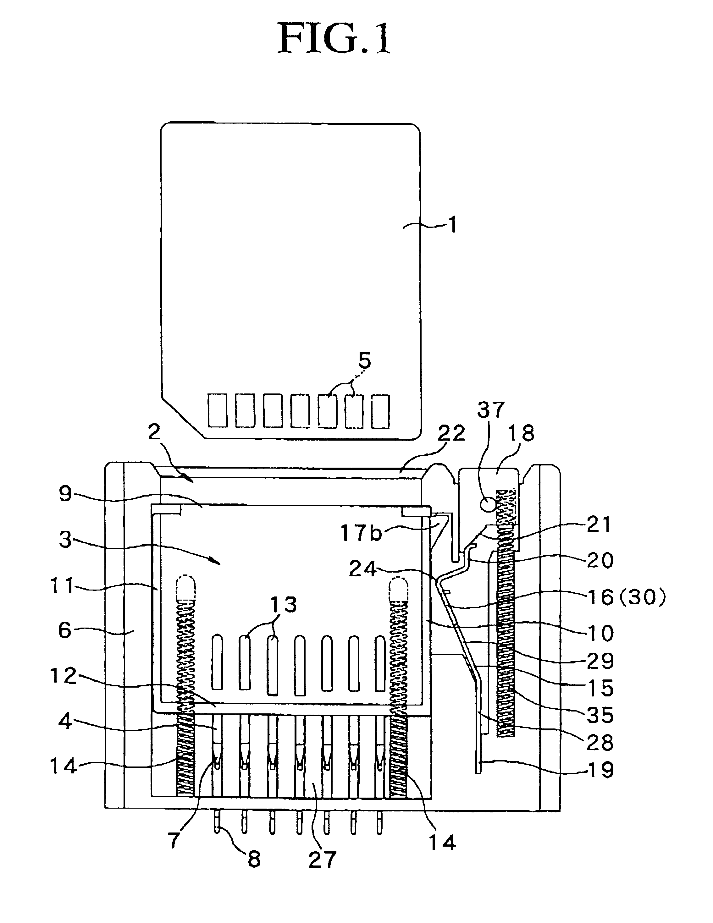
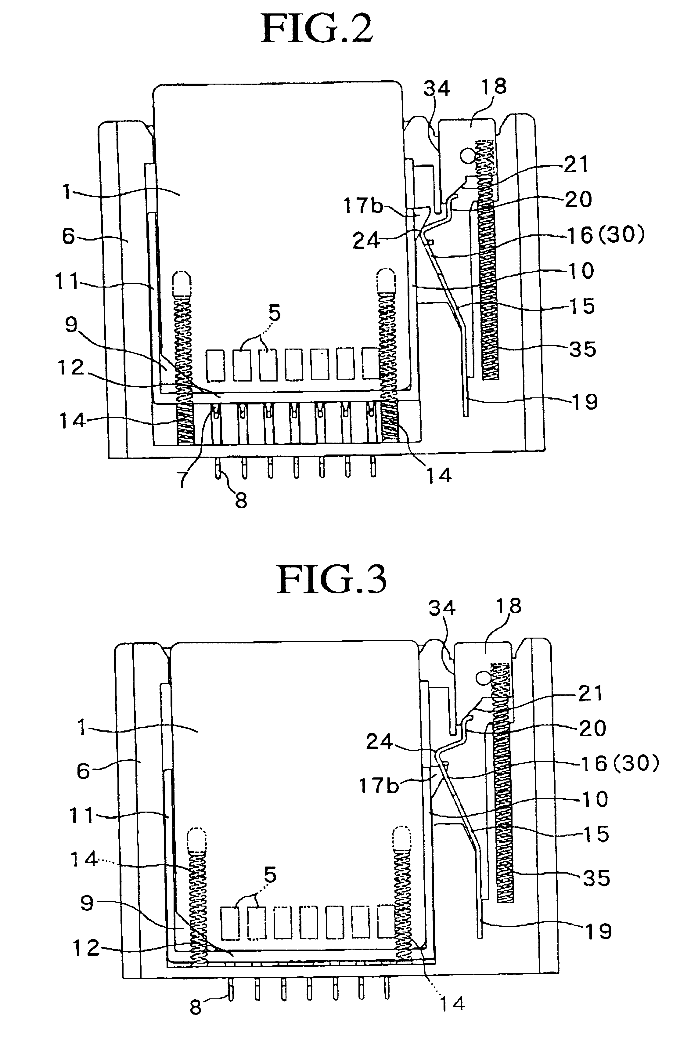
FIGS. 1 to 9 exemplify a lock and lock releasing mechanism according to one embodiment of the present invention, in which a lock arm 15 is brought into engagement with and disengagement from a card ejecting member, while FIGS. 10 to 16 exemplify another type of a lock and lock releasing mechanism, in which a lock arm 15 is brought into engagement with and disengagement from an IC card 1.

The IC card 1 is of the type having an IC chip, which is inserted into a given electronic device such as, for example, a personal computer, in order to record thereon information from the electronic device or to input information, which the IC card 1 possesses, on the electronic device. The IC card 1 includes one which contains therein a CPU.

The IC card 1 is provided with external contacts 5 which, when the IC card 1 is inserted into a card receiving space 3 through a card inlet port 2, are pressure contacted with contacts 4 arranged within the card receiving space 3.

The contacts 4 are implanted in a...


PUM


Abstract

A lock and lock releasing mechanism for an IC card connecting mechanism comprising a resilient lock arm for accumulating a preliminary resilient force by being resiliently contacted with one side edge of an IC card to be received in a card receiving space through a card inlet port of the card connecting mechanism. The resilient lock arm is arranged to engage in a recess formed on the side edge of the IC card in order to establish the locked state of the IC card. The lock and lock releasing mechanism also comprises a control member that is arranged to selectively engage the resilient lock arm so that the resilient lock arm moves against its resiliency to disengage from the recess formed on the side edge of the IC card, thereby establishing a lock released state of the IC card.

Description

1. Field of the InventionThis invention relates to a lock and lock releasing mechanism in an IC card connecting mechanism in which an IC card is inserted into a card receiving space through a card inlet port so that external contacts of the IC card are electrically connected to contacts arranged within the card receiving space, and more particularly to a lock and lock releasing mechanism in which a locked state for retaining an IC card in an inserting position and a lock released state for permitting the IC card to be ejected are established.2. Related ArtThere is known a mechanism which is disclosed, for example, in Japanese Patent Unexamined Publication (Kokai) No. Hei 10-21350 in which when an IC card is inserted into a card receiving space through an IC card inlet port, a card ejecting member is pressed by a front end face of the IC card to thereby establish an ejection standby state, an engagement portion of a resilient lock member is resiliently contacted with one side surface...

Claims


Application Information

Patent Timeline
Patent Type & Authority Patents(United States)
IPC IPC(8): G06K13/02G06K13/08H01R13/633G06K17/00H01R13/629
CPCG06K13/08G06K13/0806H01R13/6335G06K13/0856Y10S439/923
Inventor NISHIMURA, TAKESHI
Owner YAMAICHI ELECTRONICS
Why Eureka
Try Eureka