
Stand for supporting a musical instrument

a technology for musical instruments and stands, applied in the direction of instruments, machine supports, music aids, etc., can solve the problems of affecting the stability of instruments, and affecting the sound quality of instruments

Inactive Publication Date: 2002-07-23
WOOLLEN JEFFREY K
View PDF23 Cites 49 Cited by
  • Summary
  • Abstract
  • Description
  • Claims
  • Application Information

AI Technical Summary

Problems solved by technology

Musicians are often faced with the challenge of temporarily supporting their instrument when it is not being played.
Instruments such as guitars are subject to potential damage if simply laid flat on the floor, so it is common practice to lean the neck or head of the instrument against a piece of furniture or a wall.
Leaning the neck of such an instrument against a piece of furniture or the like often results in the upper part of the instrument sliding laterally, causing the entire instrument to fall to the floor, again resulting in damage to the instrument.
Leaning the head of such an instrument against a wall or a piece of furniture has the added disadvantage of potentially putting the instrument out of tune due to the tuners in the head coming in contact with the wall or furniture.
While some of these stands are collapsible to some degree, they still represent an additional piece of equipment the musician must deal with, requiring time, effort and space to transport, store, deploy and use.
In addition, neither addresses the fact that many guitars and other like instruments have back surfaces which are bowed rather than flat.
One such device, U.S. Pat. No. 5,197,701 by Olson is a mechanically complex device.
In the case of the guitar or other similar instrument, there is no practical way to hold the instrument to apply an opposing force necessary to accomplish this act.
These instruments can easily be held by their neck, but this would be difficult due to the leverage provided by the length of the neck. it is not easy to adequately grip such an instrument in the midst of it's body, where the opposing force is required.
In addition to the disadvantage of this difficulty in returning the collapsible legs to their stored position, the device suffers from an overly complex mechanical design, causing a number of other disadvantages: (a) The tooling, manufacture and assembly for the device would be expensive.
The labor required to assemble the numerous parts would be relatively costly.
(b) The mechanical complexity of the device would render it subject to potential breakdowns requiring repair or replacement.
(d) The mechanical complexity of the device contributes to an overall bulky and obtrusive appearance.
(e) The straight legs and housing would not accommodate the curvature of a bowed-back instrument, rendering the device useless on said instruments.
The other device, U.S. Pat. No 4,693,161 by Uhrig, is a simpler device, but suffers from several major disadvantages: (a) The device is attached to the musical instrument by the means of the screws which hold the neck of the instrument to the instrument body.
Loosening these screws in order to mount the device can cause misalignment of the neck and body of the instrument, resulting in a number of functional problems in the instrument.
(b) The supporting leg(s) is not spring mounted, thus manual manipulation is required for both deployment and collapsing of the device. while this solves one of the problems of the device previously cited, it adds another level of inconvenience to the user.
(d) The requirement of attaching the device at the point where the neck meets the body of the instrument requires the device span the entire length of the instrument body, resulting in a device that is both bulky and obtrusive.
(e) The straight legs would not accommodate the curvature of a bowed-back instrument, rendering the device useless on said instruments.
(g) The attachment by means of screws to any location on an instrument other than where screws already exist would result in the defacing of the instrument.

Method used


Image

  • Stand for supporting a musical instrument
  • Stand for supporting a musical instrument
  • Stand for supporting a musical instrument

Examples


Embodiment Construction

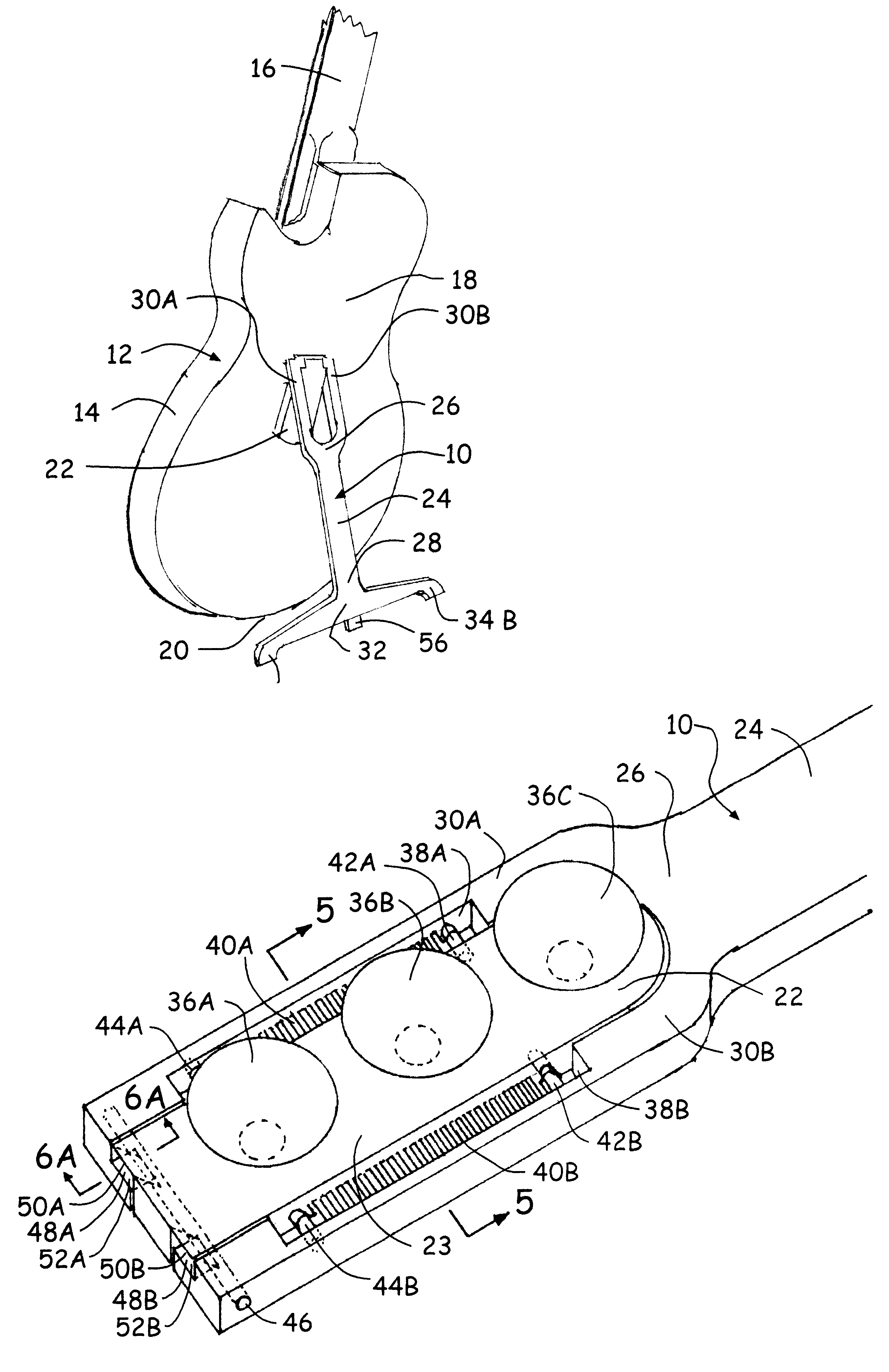
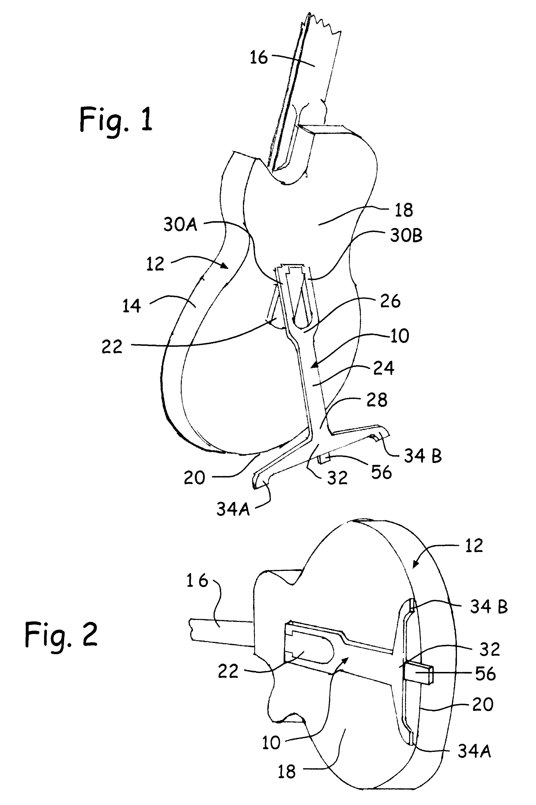
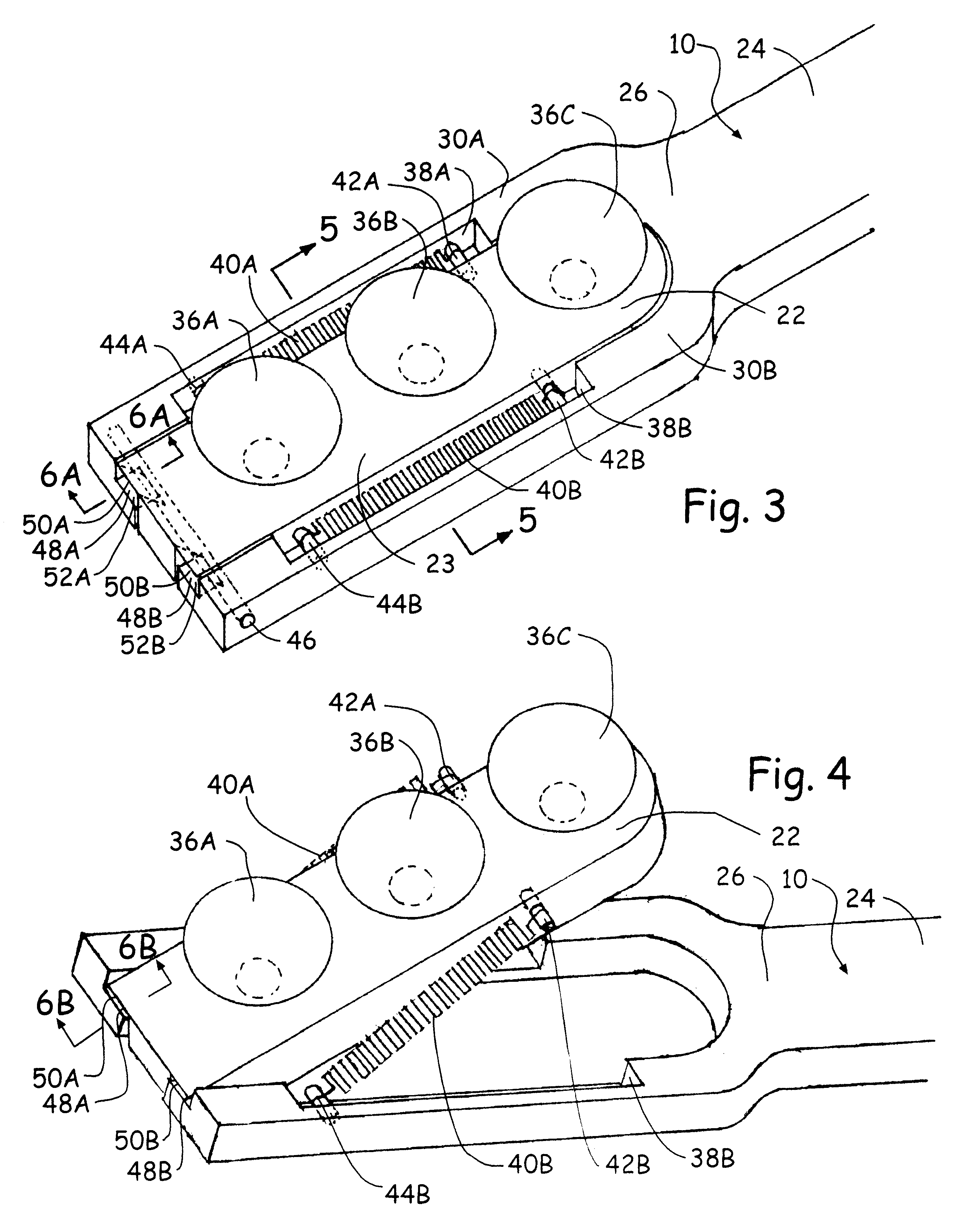
To use the instrument stand 10, one first attaches stand 10 to back surface 18 of instrument 12 by depressing suction cups 36A, B & C against back surface 18. Position ing of the stand 10 relative to instrument body 14 is such that foot portionsb lie approximately even with instrument rear surface bottom edge 20, while the tip of third foot portion 56 overhangs bottom edge 20 by a short distance.

As illustrated in FIG. 8A, once stand 10 has been attached, one holds the instrument 12 by gripping neck 16, positioning instrument 12 in a generally upright position above the floor or other supporting surface. In this position, instrument 12 is lowered until third foot portion 56 comes into contact with the floor or other supporting surface, as shown in FIG. 8B, where friction between the tip of third foot portion 56 and said floor fixes the position of third foot portion 56 relative to said floor. Now, as shown in FIG. 8C, instrument 12 is pivoted along the centerline of pin 46 as the bot...


PUM


Abstract

A stand (10) for supporting a musical instrument (12), such as a guitar, in an upright position when not in use and for retention on the instrument when the instrument is in use. The stand comprises a mounting base (22) secured to the rear surface of the instrument (18), and a support member (24) pivotally connected to the mounting base (22) and containing first and second foot portions (34A & B) and third foot portion (56). The pivotal attachment allows the support member (24) to be transitioned between a storage position adjacent the rear surface of the instrument (18) and a deployed position spaced away from the rear surface of the instrument (18) where, together with the bottom edge of the instrument (20), the first and second foot portions (34A & B) act to support the instrument (12). Third foot portion (56) engages a floor or other support surface providing fixative force to the support member allowing the instrument and mounting base to be pivoted away from the support member to the deployed position without the need to touch the stand. The support member (24) is spring-loaded and automatically returns to the storage position when the instrument (12) is lifted for use.

Description

CROSS-REFERENCE TO RELATED MATERIALNot applicable.BACKGROUND--FIELD OF INVENTIONThis invention relates to musical instrument stands, specifically to a musical instrument stand for enabling the instrument to remain in an upright position when not in use and which is retained on the instrument when the instrument is in use.BACKGROUND--DESCRIPTION OF PRIOR ARTMusicians are often faced with the challenge of temporarily supporting their instrument when it is not being played. Instruments such as guitars are subject to potential damage if simply laid flat on the floor, so it is common practice to lean the neck or head of the instrument against a piece of furniture or a wall.Leaning the neck of such an instrument against a piece of furniture or the like often results in the upper part of the instrument sliding laterally, causing the entire instrument to fall to the floor, again resulting in damage to the instrument. Leaning the head of such an instrument against a wall or a piece of furnit...

Claims


Application Information

Patent Timeline
IPC IPC(8): G10G5/00
CPCG10G5/00
Inventor WOOLLEN, JEFFREY K.
Owner WOOLLEN JEFFREY K
Learn More