Single cam operated attachment device

a single cam and attachment device technology, applied in the field of single cam operated attachment devices, can solve the problems of slipping or spinning, affecting the retention of the sight to the weapon, and many mechanical problems, and achieve the effect of stabilizing the sigh

Inactive Publication Date: 2002-09-03
L 3 COMM CORP
View PDF14 Cites 132 Cited by
  • Summary
  • Abstract
  • Description
  • Claims
  • Application Information

AI Technical Summary

Benefits of technology

The purpose of the present invention is to provide a mount that secures a sighting or viewing system to the mounting rail of a weapon, and has an adjustable support to help stabilize the sight.

Problems solved by technology

The sequence of locking may cause many problematic mechanical effects.
When the second lock is activated, this works against the first lock causing it to slip or spin.
The inherent problem with the above mentioned mounting system is consistency.
The above problem can negatively influence bore-sight retention of the sight to the weapon.
If this not performed properly, the sheetmetal guard gets trapped between the mount and the weapon rail causing improper installation of the mount and possibly permanently deform the sheetmetal guard.
An additional disadvantage to the known two-lock system is the short and straight levers that operate the cam locks.
The straightness of the levers can make it difficult to grab because they are too close to the mount.
The short length of the levers does not provided adequate mechanical advantage, and is difficult to lock and unlock.
When two machine screws are used, this second system has all the same problems as the first.
However, it does not have the problem of a lever that is hard to reach or having a lack of mechanical advantage.
An additional disadvantage to the machine screw operated locking mechanism system, whether single or double, is the time required to secure the mount and inconsistent loading.
This method can be very time consuming.
It is also hard to hand torque a screw to provide a consistent clamping force.
This torque limiting mechanism may have a noisy operation, and is not desirable when silence is required.
The mechanism protrudes to the side of the mount, and is susceptible to damage during accidental impact, such as when dropped or accidental contact with any foreign objects.
The inconsistent load issue is not adequately addressed by these torque limiting mechanisms; the user can greatly increase the resultant torque by applying an inward axial load while turning the knob.
Also, time required to operate the screw mechanisms in not addressed.

Method used


Image

  • Single cam operated attachment device
  • Single cam operated attachment device
  • Single cam operated attachment device

Examples


Embodiment Construction

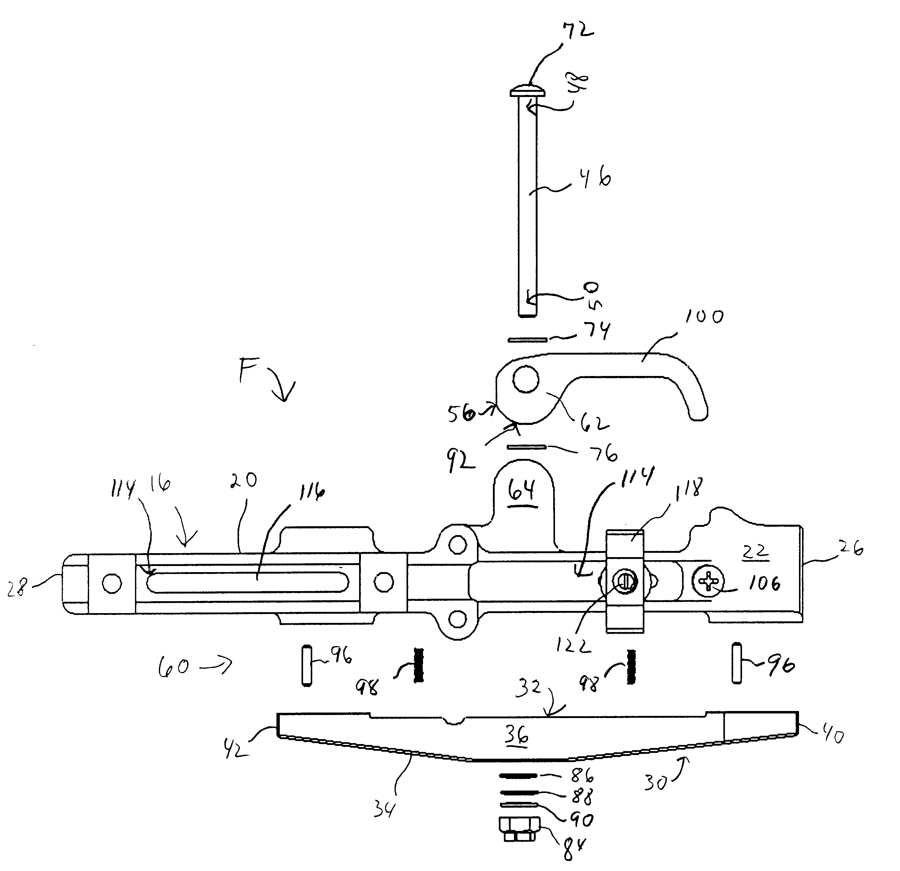
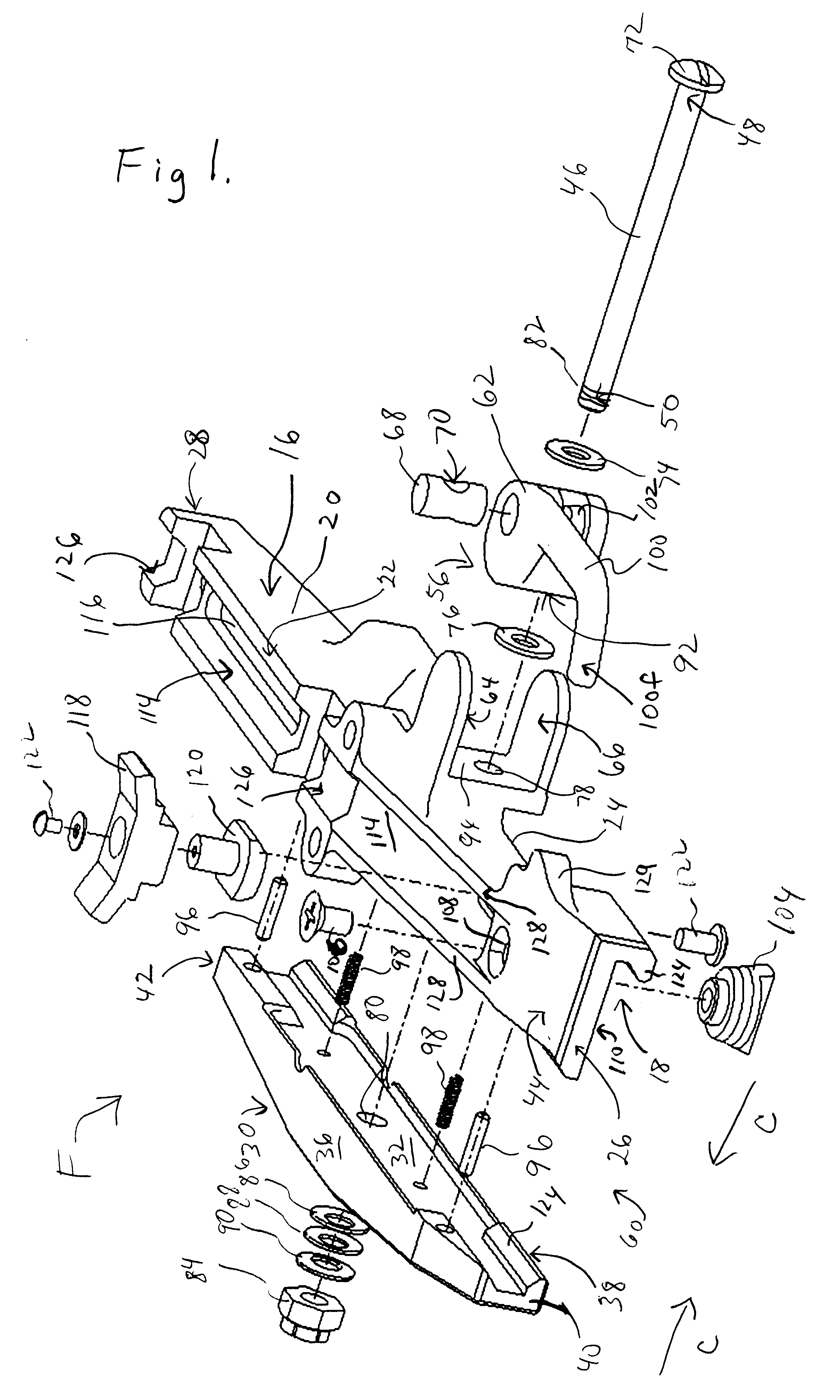
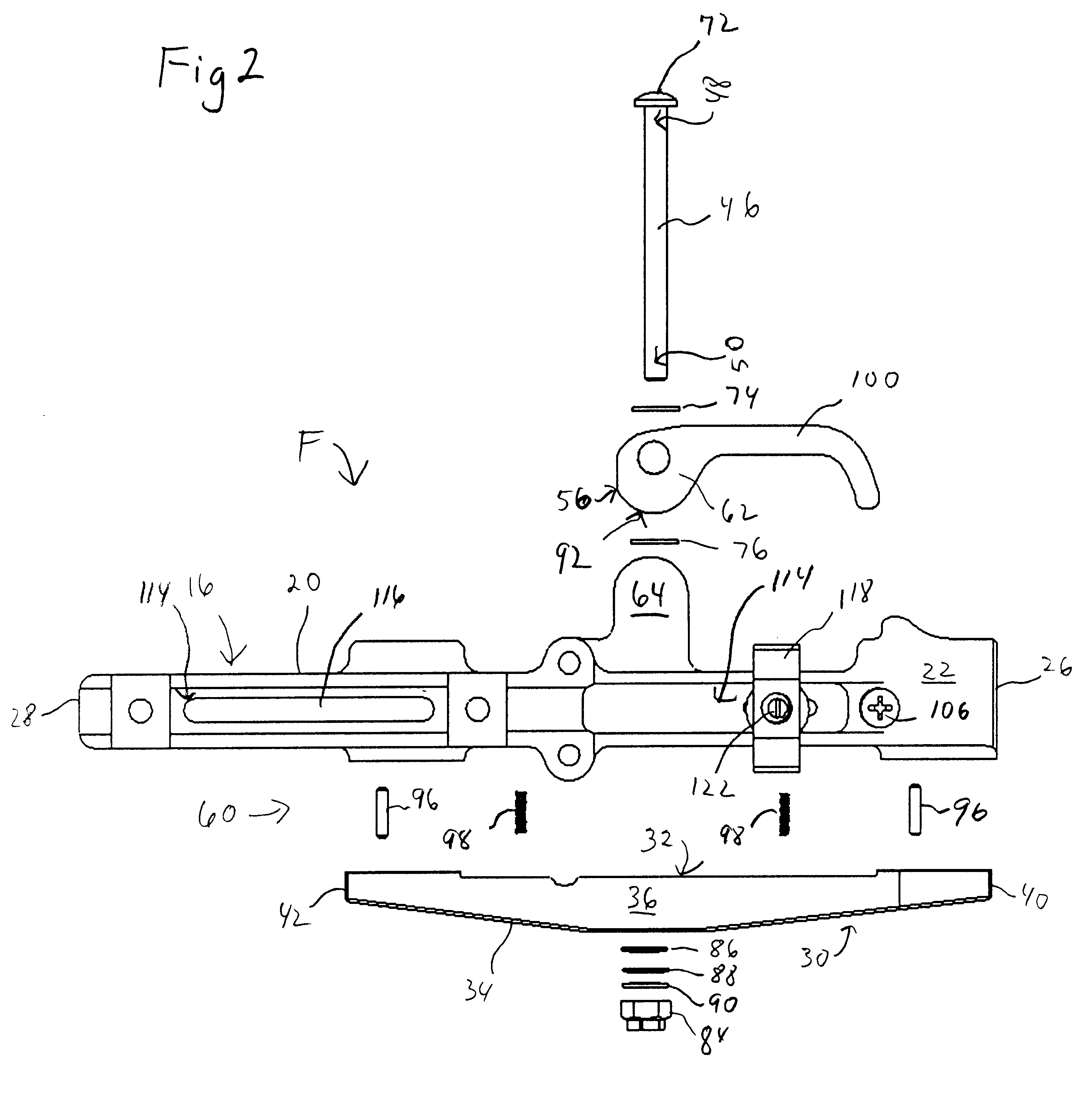
So that the manner in which the above recited features, advantages and objects of the present invention are attained can be understood in detail, more particular description of the invention, briefly summarized above, may be had by reference to the embodiment thereof that is illustrated in the appended drawings. In all the drawings, identical numbers represent the same elements.

The fastening device (F) of the present invention for attaching a selected first device (10) to a mounting or mating rail member (12) of a second device (14) includes a first side member (16) that has an interior surface (18) and an exterior surface (20), an upper longitudinal edge (22) and lower-longitudinal edge (24), and a first front edge (26) and second rear edge (28). Similarly, a second side member (30) has an interior surface (32) and an exterior surface (34), an upper longitudinal edge (36) and lower longitudinal edge (38), and a first front edge (40) and second rear edge (42). A top section (44) ext...


PUM


Abstract

A fastening device (F) with first (16) and second sides (30) attaches a first device (10) to a mounting rail (12) of a second device (14). A top section (44) for mounting the first device extends from the first or second sides. The sides are adapted to removably clamp about the rail. A clamping member (46) extends between the first and second sides. An extended end (48) of the clamping member extends through the first side, and an opposing end (50) is coupled with the second side. The clamping member extended portion (48) is movably coupled to a single cam member (56) operably mounted with the first side for drawing the sides closer together into a clamping position (58) to mate the sides with the rail.

Description

1. Technical FieldThe invention relates to the field of attachment means, and more particularly to a mount for attaching devises to a weapons mount such as one meeting the US MIL-STD-1913 standard or other type of railing.2. Background ArtKnown systems to attach or fasten various devices to weapons rails include at least 3 different types. A first known type includes a mount that uses two cam operated locking mechanisms, one forward and the other aft. A second type of attachment means includes a mount that uses a machine screw operated locking mechanism, either single or double with one forward and the other aft. A third type of known attachment means is a variation of the second: a mount that uses a torque limiting device in or under the knob of the machine screw(s).The first type of mount has a two-cam locking method that locks one side of the mount to a weapon rail first and then locks the second side. The sequence of locking may cause many problematic mechanical effects. For exa...

Claims


Application Information

Patent Timeline
Patent Type & Authority Patents(United States)
IPC IPC(8): F41G1/387F41G1/00
CPCF41G11/003
Inventor WATERMAN, MICHAEL D.KEEPERS, CURTIS B.WANNAGOT, GARY A.CONNORS, CLIFFORD J.
Owner L 3 COMM CORP
Why Eureka
Try Eureka