Cutting insert with cooling channel

a cooling channel and cutting insert technology, applied in the direction of cutting inserts, manufacturing tools, shaping cutters, etc., can solve the problems of insufficient cooling and chip flow, inability to feed cooling liquid in the form of jets, and large heat generation

Inactive Publication Date: 2002-09-10
SANDVIK INTELLECTUAL PROPERTY AB
View PDF12 Cites 111 Cited by
  • Summary
  • Abstract
  • Description
  • Claims
  • Application Information

AI Technical Summary

Benefits of technology

is, therefore, to provide a cutting insert which permits access of high-pressure liquid jets to the area below the zone along which the chip is separated from the cutting insert, at the same time as the chip should be broken out from the top side of the cutting insert as ef

Problems solved by technology

When a cutting insert during, for instance, turning cuts loose a chip from a rotating workpiece, usually of metal, considerable amounts of heat are generated.
However, the attempts to improve the cooling and the flow of the chip away from conventional cutting insert carrie

Method used


Image

  • Cutting insert with cooling channel
  • Cutting insert with cooling channel
  • Cutting insert with cooling channel

Examples


Embodiment Construction

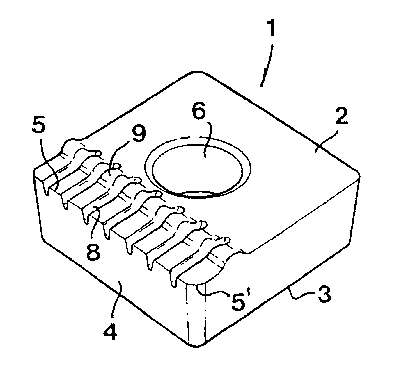
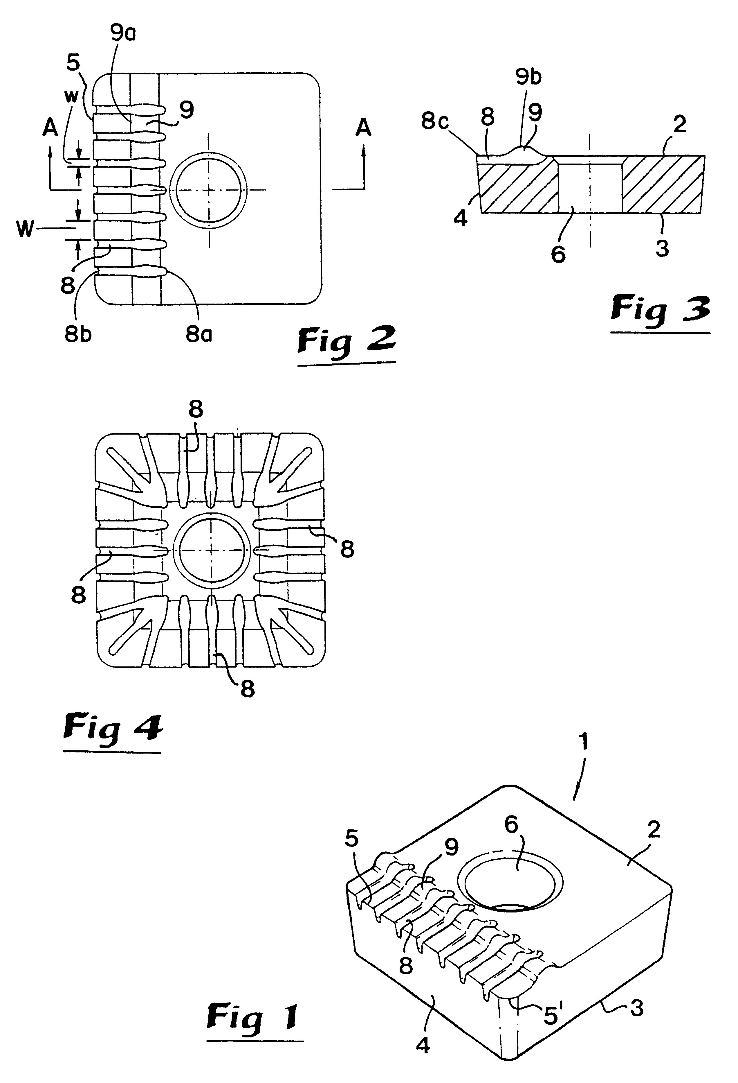
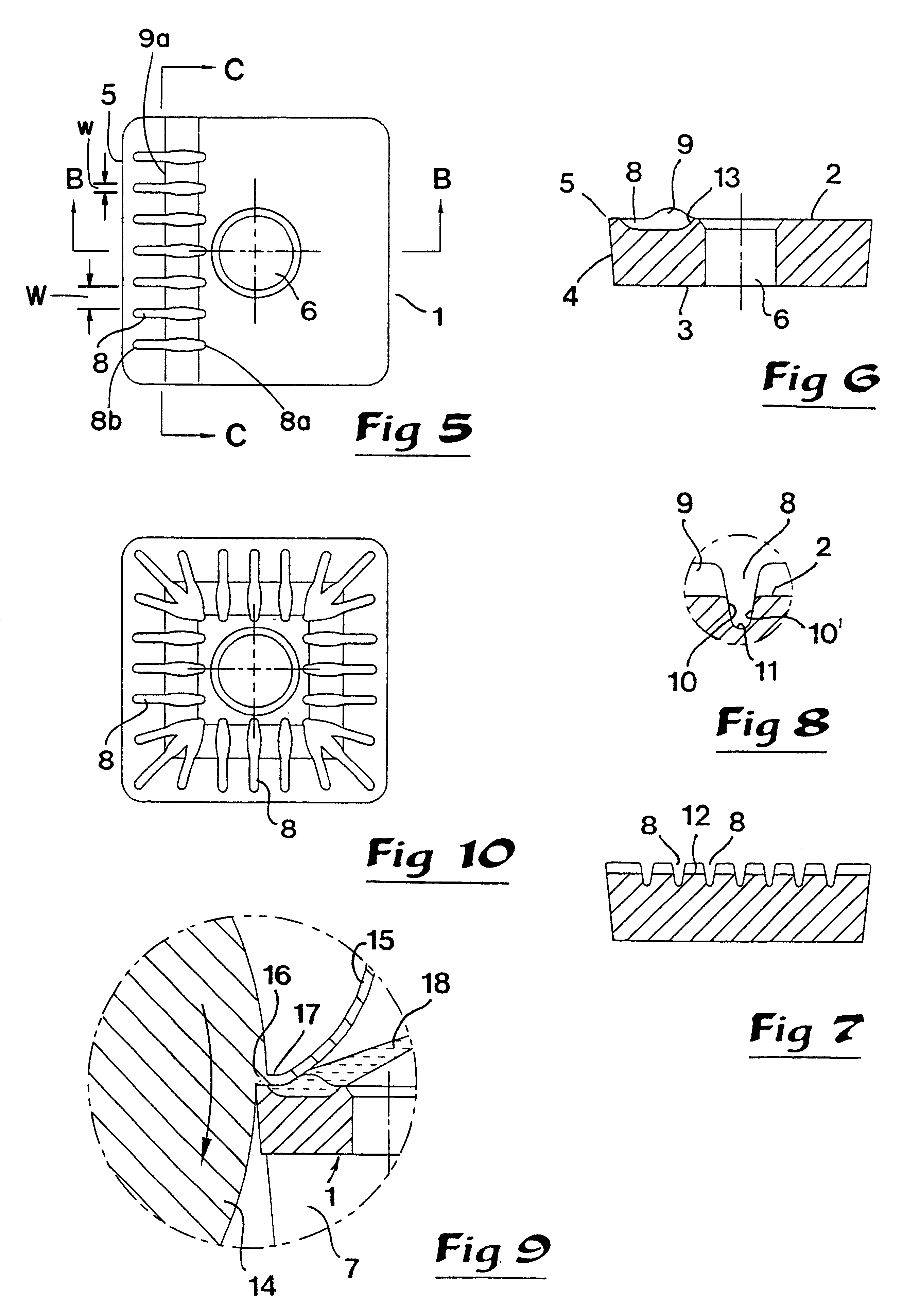
In FIGS. 1-3 a cutting insert 1 is shown, which is delimited by a top side 2, a bottom side 3 as well as a number of side surfaces 4 extending therebetween. In the example shown, the number of side surfaces is four. Thus, the insert is of polygonal shape as viewed in top plan. There is a cutting edge 5 between the top side 2 and a side surface 4, which serves as a flank. At the corners of the cutting insert, the straight cutting edge portion 5 transforms into a rounded cutting edge portion 5'. In the generally square-shaped cutting body, there is a central hole 6 for a fixing screw (not shown), by means of which the cutting insert may be fastened in a seat of a cutting tool, e.g. for turning. Parts of this tool are outlined at 7 in FIG. 9.

A number of mutually separated grooves 8, are provided in connection with the cutting edge 5 and said grooves open upwards in the top side of the cutting insert. Projections 9 are arranged between adjacent grooves 8 in a manner which is characteris...


PUM

PropertyMeasurementUnit
Shapeaaaaaaaaaa
Widthaaaaaaaaaa
Depthaaaaaaaaaa

Abstract

A cutting insert for chipforming machine has a tip face with a cutting edge. Grooves are formed in the top face and extend toward the cutting edge. Chip-deflecting projections extend upwardly from the top face and are situated in spaces formed between adjacent grooves. A jet of cooling fluid is directed toward inner ends of the grooves and travels between the projections and within the grooves toward the cutting edge.

Description

This invention relates to a cutting insert intended for chip removing machining, which is delimited by a top side, a bottom side and a number of side surfaces extending therebetween, and which has at least one cutting edge between said top side and a side surface serving as a flank. Grooves which are mutually separated and open upwards, are provided in said top side, in connection with the cutting edge, for feeding cooling liquid in the direction towards the cutting edge.GENERAL BACKGROUND OF THE INVENTION AND PRIOR ARTThe practice of cooling not only the cutting inserts of cutting tools, e.g. tools for turning, but also the workpiece being machined by the tool as well as the chip being cut from the workpiece has been known for a long time. A fundamental aim within the technology of today for cutting machining is to enable the use of the highest possible pressure in the cooling liquid and to supply the liquid in the form of one or more jets mainly directed towards the cutting insert...

Claims


Application Information

Patent Timeline
IPC IPC(8): B23B27/14B23B27/00B23B27/10
CPCB23B27/10B23B27/143B23B2200/086Y10T407/235Y10T407/245Y10T407/24B23B2200/205
Inventor LAGERBERG, STIG
Owner SANDVIK INTELLECTUAL PROPERTY AB
Why Eureka
Try Eureka