Battery module, and connecting structure of cells in the battery module

a battery module and battery module technology, applied in secondary cells, cell components, cell components, etc., can solve the problems of large electrical resistance at the connection, inability to compact the space for installing this battery pack, and relatively high cos

Inactive Publication Date: 2002-09-24
PANASONIC CORP +1
View PDF12 Cites 64 Cited by
  • Summary
  • Abstract
  • Description
  • Claims
  • Application Information

AI Technical Summary

Problems solved by technology

As the connection between adjacent cells requires a complicated structure with a large number of components, costs are relatively high, and the electrical resistance at the connection is large.
Moreover, since it is necessary to provide a space for the connection structure above the battery case 42, and since the connection structure is exposed to the outside, the space for installing this battery pack cannot be made compact.

Method used


Image

  • Battery module, and connecting structure of cells in the battery module
  • Battery module, and connecting structure of cells in the battery module
  • Battery module, and connecting structure of cells in the battery module

Examples


Embodiment Construction

Preferred embodiments of a battery module according to the present invention will be hereinafter described with reference to FIGS. 1 to 7.

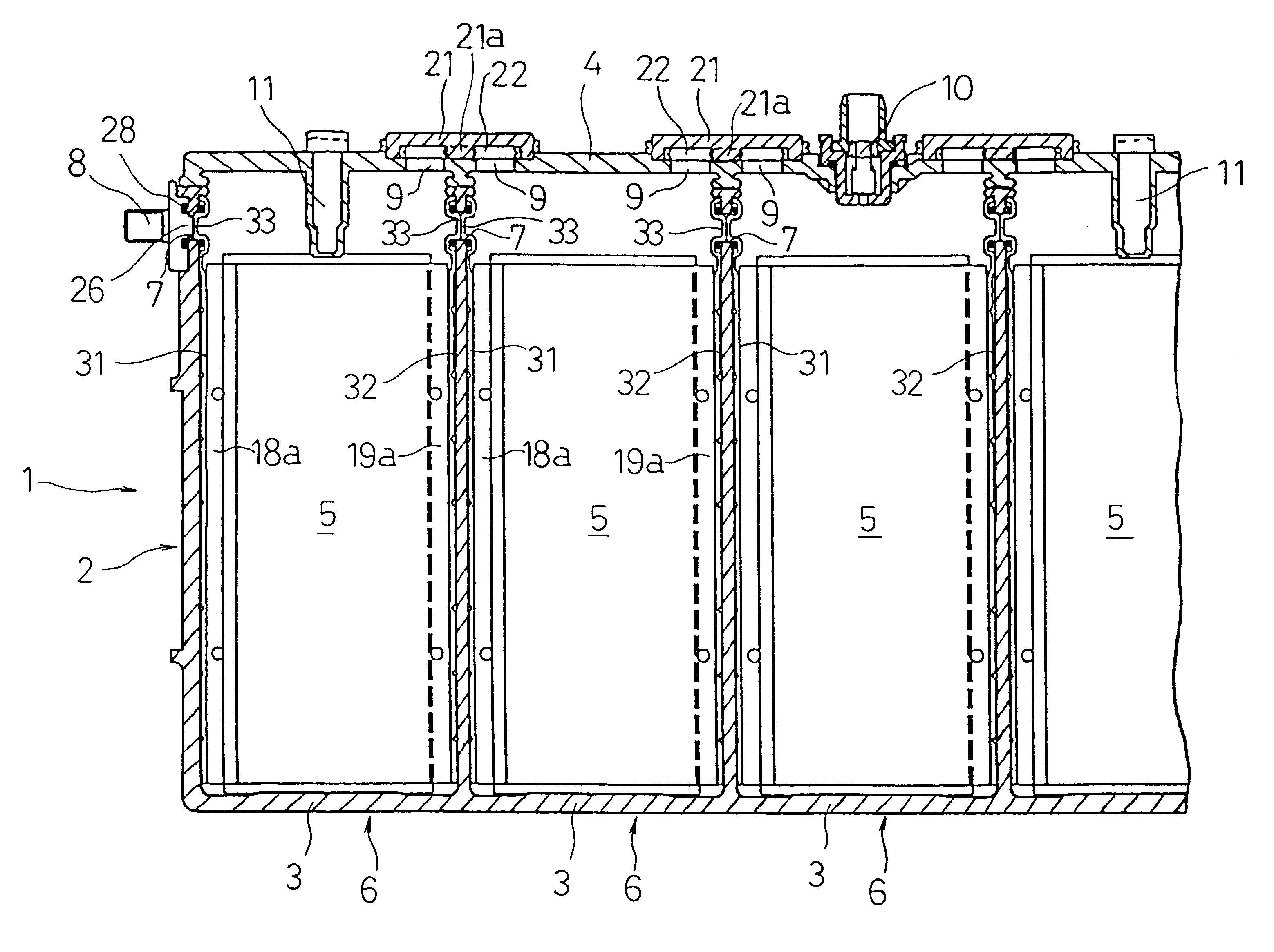
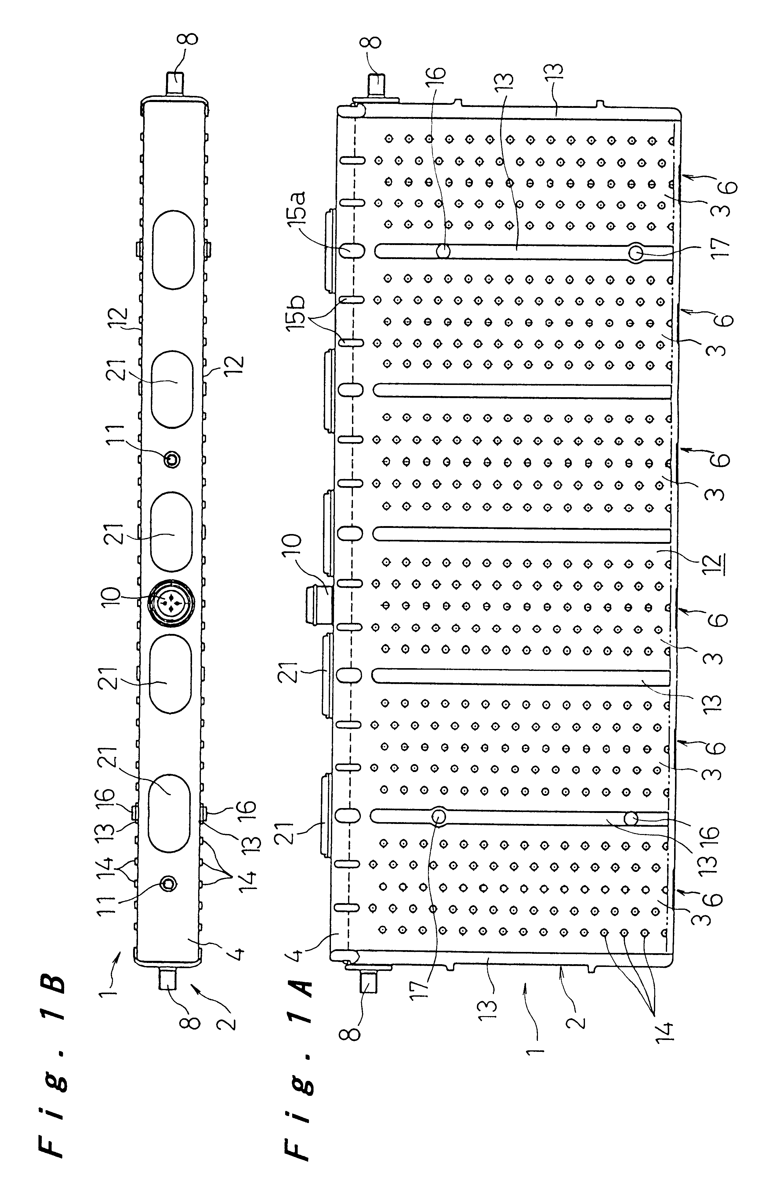
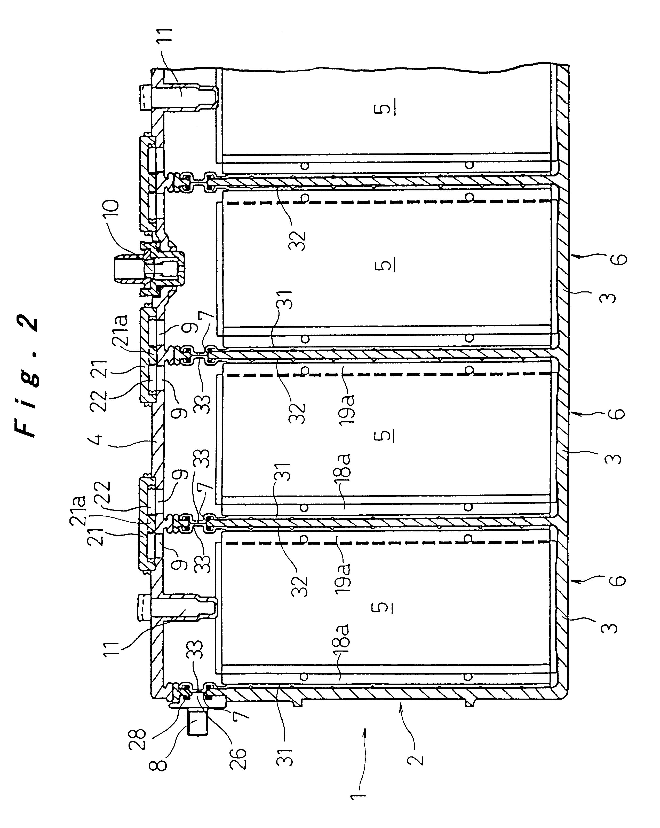
The battery module of this embodiment is a nickel metal hydride battery, which is suitable for use as a drive power source for an electric vehicle. As shown in FIGS. 1 and 2, the battery module 1 is made up of a plurality of (six in the example shown in the drawing) cells 6, arranged in a row. Cell cases 3 of each of the cells 6, which are formed in a prismatic fashion with short lateral walls, long lateral walls, and open top ends, are mutually integrated on their short lateral walls, thereby constituting an integral battery case 2. The upper open ends of the cell cases 3 are closed all together by an integral lid member 4.

Each of the battery cases 3 constitutes a cell 6, accommodating therein electrode plate groups 5 together with electrolyte. An electrode plate group 5 comprises a large number of positive electrode plates and negative electrode...


PUM

PropertyMeasurementUnit
polarityaaaaaaaaaa
poweraaaaaaaaaa
electromotive forceaaaaaaaaaa

Abstract

The battery module comprises a plurality of cells encased in prismatic cell cases having short lateral walls and long lateral walls coupled together as one piece. Each of the cells accommodates therein a group of electrode plates and liquid electrolyte, wherein collector plates are connected respectively to the groups of positive and negative electrode plates at opposite lateral edges thereof. Connection holes are formed at upper edge portions of the short lateral walls of the cell cases, and the collector plates are formed with connection bosses that fit into the connection holes, so that the connection bosses of the collector plates in neighboring cells are abutted each other and welded together, whereby two adjacent cells are connected to each other.

Description

1. Field of the InventionThe present invention relates to a rechargeable battery, and more particularly, to a rechargeable battery that can be suitably applied for a battery module in which a plurality of such rechargeable battery cells are connected in series.2. Description of Related ArtFIG. 11 shows a conventional battery pack made by connecting a plurality of rechargeable batteries and coupling them together as one so as to obtain a necessary power. In this battery pack, a plurality of cells 41 (41a to 41j) made of sealed alkaline rechargeable batteries as shown in FIG. 12 are arranged in a row, with the long lateral walls of the battery cases 42 adjacent each other. End plates 52 are arranged against the outside of the cells 41a and 41j at opposite ends, and the cells are coupled together as one piece with binding bands 53.For the cells 41, as shown in FIG. 12, an electrode plate group 47, comprising positive electrode plates and negative electrode plates layered with interveni...

Claims


Application Information

Patent Timeline
Patent Type & Authority Patents(United States)
IPC IPC(8): H01M2/22H01M2/24H01M2/02H01M10/34H01M10/50H01M2/12H01M10/42H01M10/30H01M50/112H01M50/529
CPCH01M2/0242H01M2/0245H01M2/24H01M10/345H01M2/0217H01M2/12H01M10/5004H01M10/5008H01M10/5032H01M10/5059H01M10/5073Y02E60/124H01M10/647H01M10/6557H01M10/617H01M10/6566H01M10/613Y02E60/10H01M50/103H01M50/112H01M50/258H01M50/30H01M50/529
Inventor INOUE, HIROSHIMATSUNAKA, NOBUYUKIKAJIYA, HIROMI
Owner PANASONIC CORP
Why Eureka
Try Eureka