Connecting structure of a fuse link and external terminals

a technology of connecting structure and fuse link, which is applied in the direction of coupling device connection, electrical apparatus construction details, engagement/disengagement of coupling parts, etc., can solve the problems of poor workability, unsatisfactory solution, and likely wrong connection of non-shown external terminals

Inactive Publication Date: 2002-09-24
YAZAKI CORP
View PDF21 Cites 28 Cited by
  • Summary
  • Abstract
  • Description
  • Claims
  • Application Information

AI Technical Summary

Problems solved by technology

With respect to the above prior art, however, the non-shown external terminals are likely to be connected to wrong positions (i.e. false assembly) because the terminals 5 and the non-shown external terminals are connected with the same couples of bolt and nut.
Referring to FIG. 9 further, though the terminal connecting bolts 17,18 can be different in size each other in order to recognize respective connecting pos

Method used


Image

  • Connecting structure of a fuse link and external terminals
  • Connecting structure of a fuse link and external terminals
  • Connecting structure of a fuse link and external terminals

Examples


Embodiment Construction

)

An embodiment of the present invention will now be described in further detail with reference to the accompanying drawings.

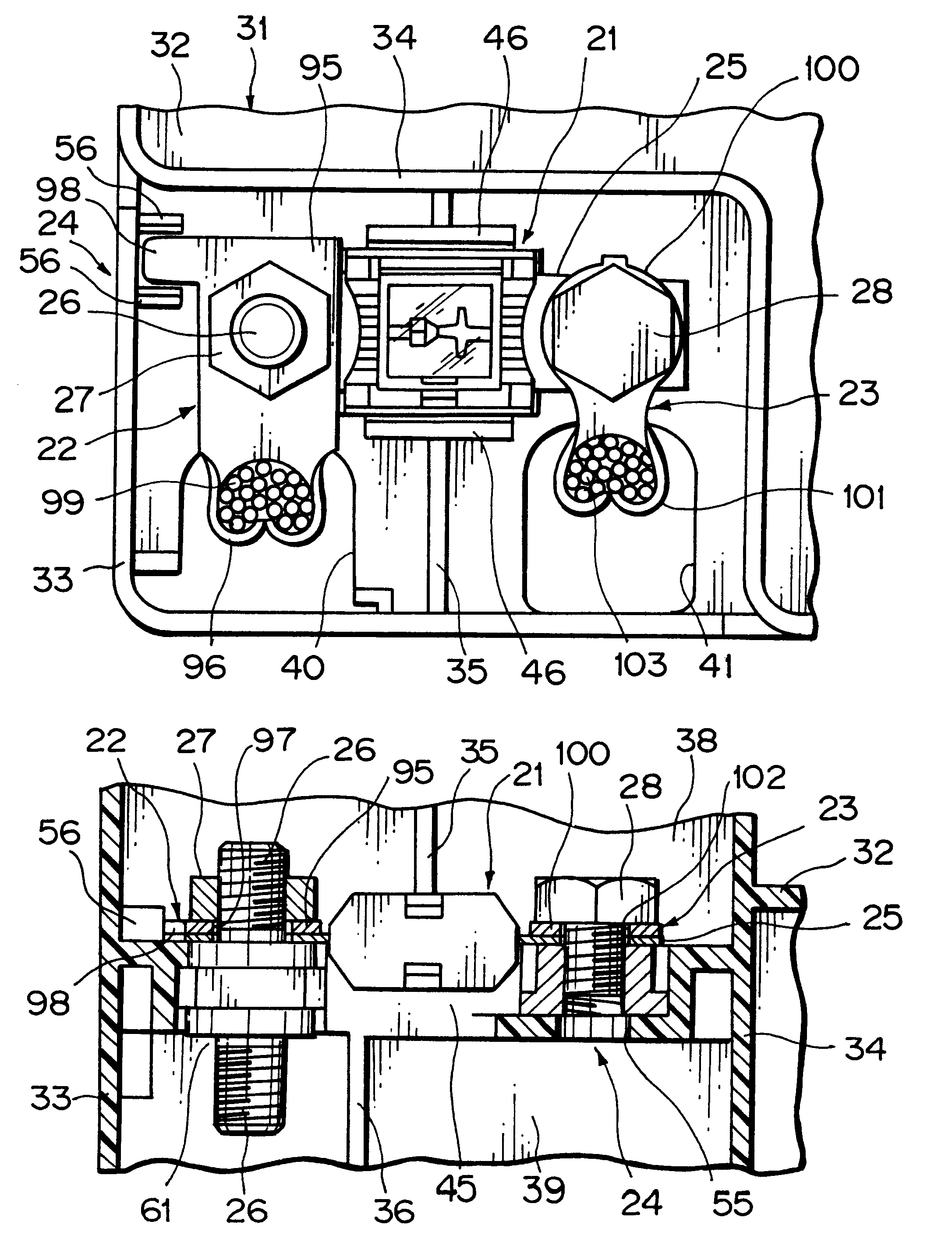
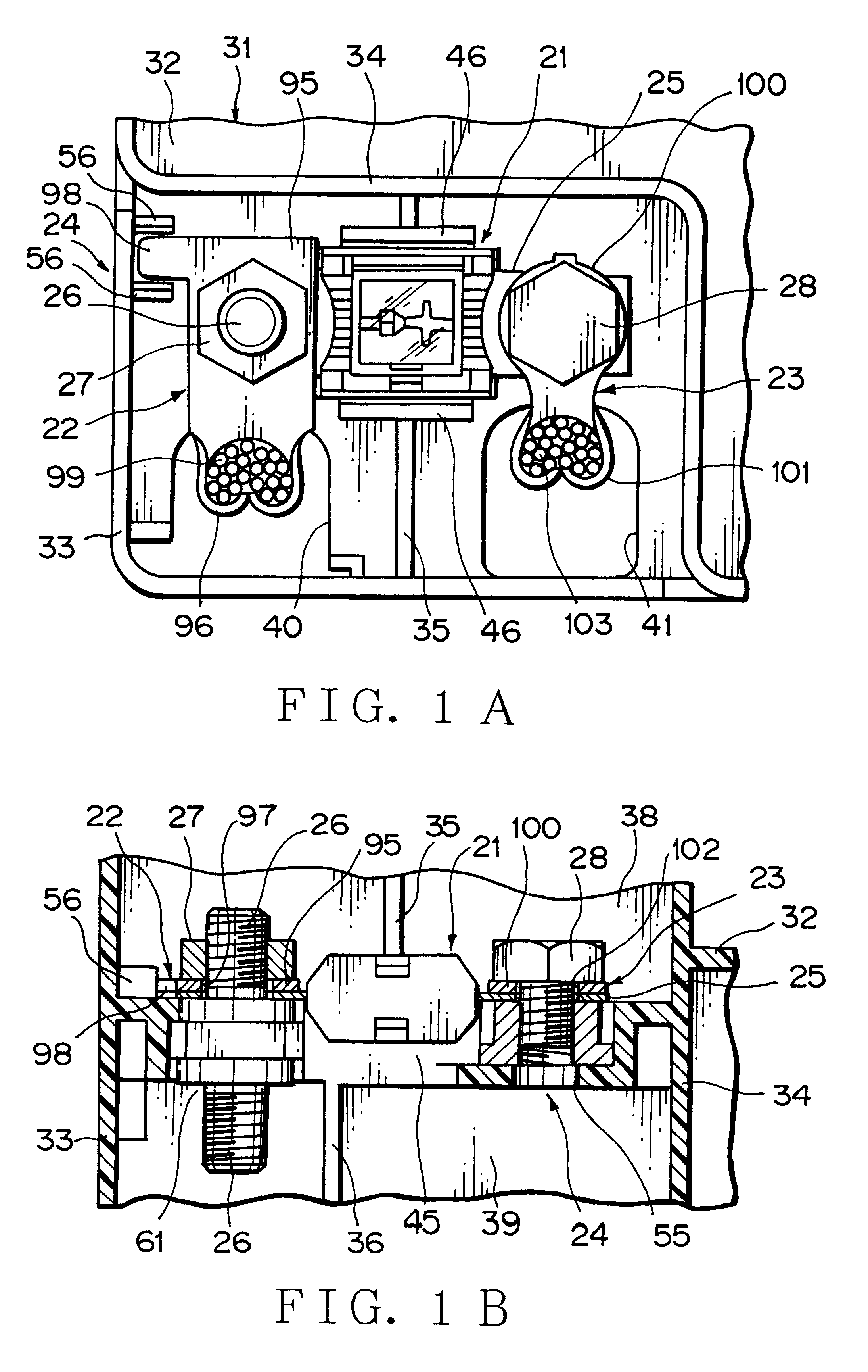
FIG. 1A is a plan view showing an embodiment of a connecting structure of a fuse link and external terminals in accordance with the present invention in a state that the external terminals are connected to the fuse link retained in a setting portion. FIG. 1B is a sectional view of the connecting structure shown in FIG. 1A

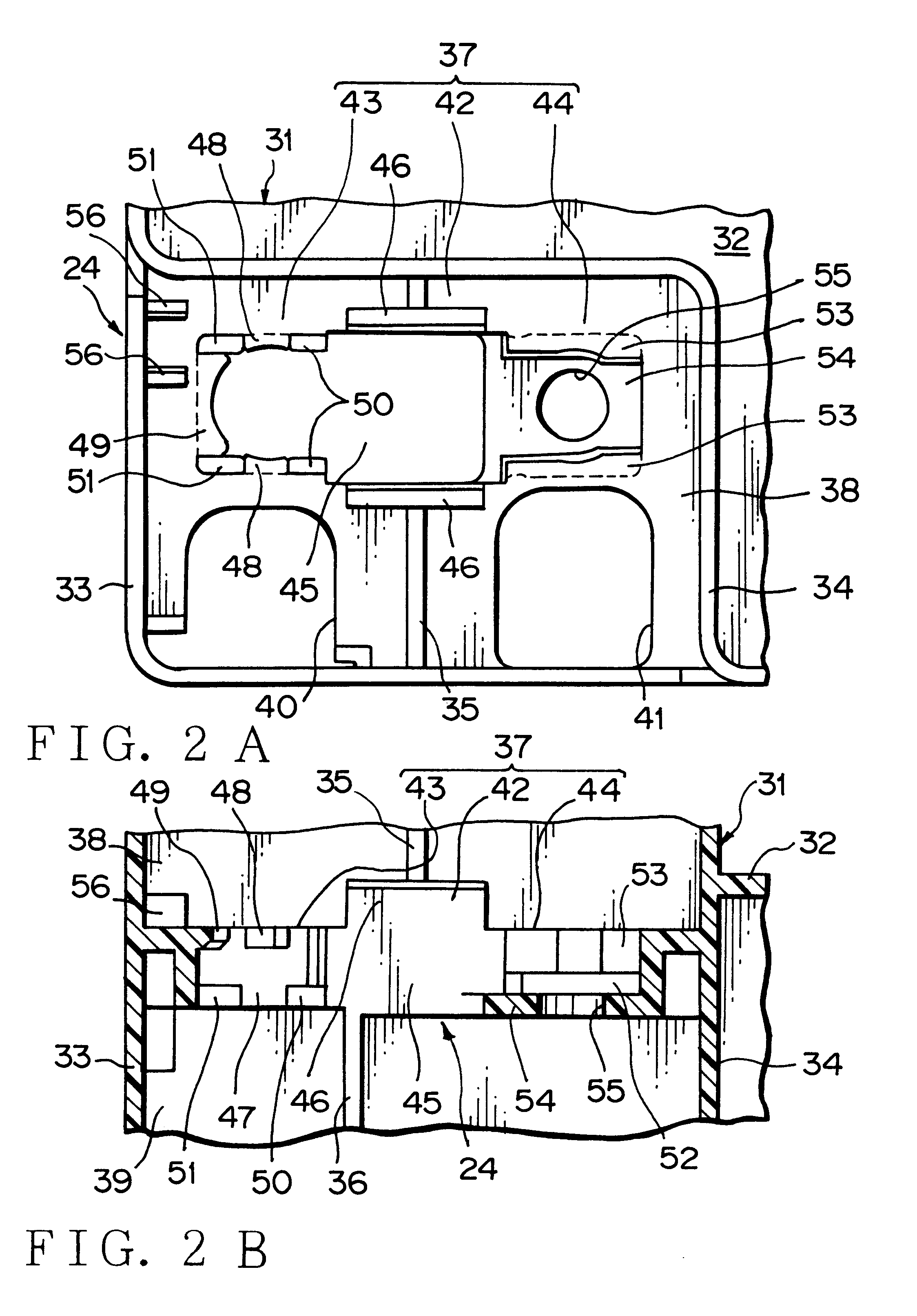
FIG. 2A is a plan view showing the setting portion, in which the fuse link is set, provided on an object to which the fuse link is attached. FIG. 2B is a sectional view of the setting portion shown in FIG. 2A. FIG. 3A is a plan view showing a first connecting member. FIG. 3B is a front view of the first connecting member shown in FIG. 3A. FIG. 4A is a plan view showing a second connecting member. FIG. 4B is a front view of the second connecting member shown in FIG. 4A. FIG. 5A is a plan view showing the fuse link. FIG. 5B is an enlarged plan vi...


PUM


Abstract

A connecting structure of a fuse link 21 and external terminals 22,23 is provided, wherein a terminal connecting nut 27 is screwed to a male threaded portion 26 projecting through a metallic fuse member 25 of the fuse link 21 retained in a setting portion 24 so as to secure the external terminal 22 to the metallic fuse member 25 in a conductive state and a terminal connecting bolt 28 is put through both of the external terminal 23 and the metallic fuse member 25 and is screwed to a female threaded portion 68 so as to secure the external terminal 23 to the metallic fuse member 25 in a conductive state.

Description

1. Field of the InventionThe present invention relates to a connecting structure of a fuse link and external terminals.2. Description of the Related ArtA connecting structure of a fuse link and external terminals shown in FIG. 9 is generally known. First, the structure is described, and subsequently the connection will be described.In FIG. 9, reference character 1 designates a fuse link already known. The fuse link 1 is detachably retained or held in a setting portion 3 of an object 2.The fuse link 1 consists of a casing 4 to cover a non-shown fuse portion made of synthetic resin and a pair of terminals 5. A bolt through hole (not shown) is formed on each of the terminals 5.The setting portion 3 has an accommodating recess 6 for the fuse link 1. Terminal through holes 8 for the terminals 5 are formed on a bottom wall 7 of the accommodating recess 6. The terminals 5 are aligned with the terminal through holes 8, and the fuse link 1 is moved toward the bottom wall 7 from an opening po...

Claims


Application Information

Patent Timeline
IPC IPC(8): H01H85/20H01H85/00H01H1/00H01H1/58H01H85/10H01H85/11H01H85/22H01H85/153H01H85/175H01H85/50H01H85/56
CPCH01H85/205H01H1/5855H01H2085/206H01H2300/044
Inventor TSUCHIYA, HIROKAZU
Owner YAZAKI CORP
Why Eureka
Try Eureka