Thermal overload relay

a relay and overload technology, applied in relays, circuit-breaking switches, snap-action arrangements, etc., can solve problems such as problems in operational characteristics of the above-described conventional structur

Inactive Publication Date: 2002-10-01
FUJI ELECTRIC FA COMPONENTS & SYST CO LTD
View PDF12 Cites 27 Cited by
  • Summary
  • Abstract
  • Description
  • Claims
  • Application Information

AI Technical Summary

Problems solved by technology

The thermal overload relay of the above-described conventional st...

Method used


Image

  • Thermal overload relay
  • Thermal overload relay
  • Thermal overload relay

Examples


Embodiment Construction

An embodiment of the present invention will be described with reference to the drawings. The members in FIGS. 1 to 3 that are the same as in the conventional example are denoted by the same reference numerals and description thereof is thus omitted.

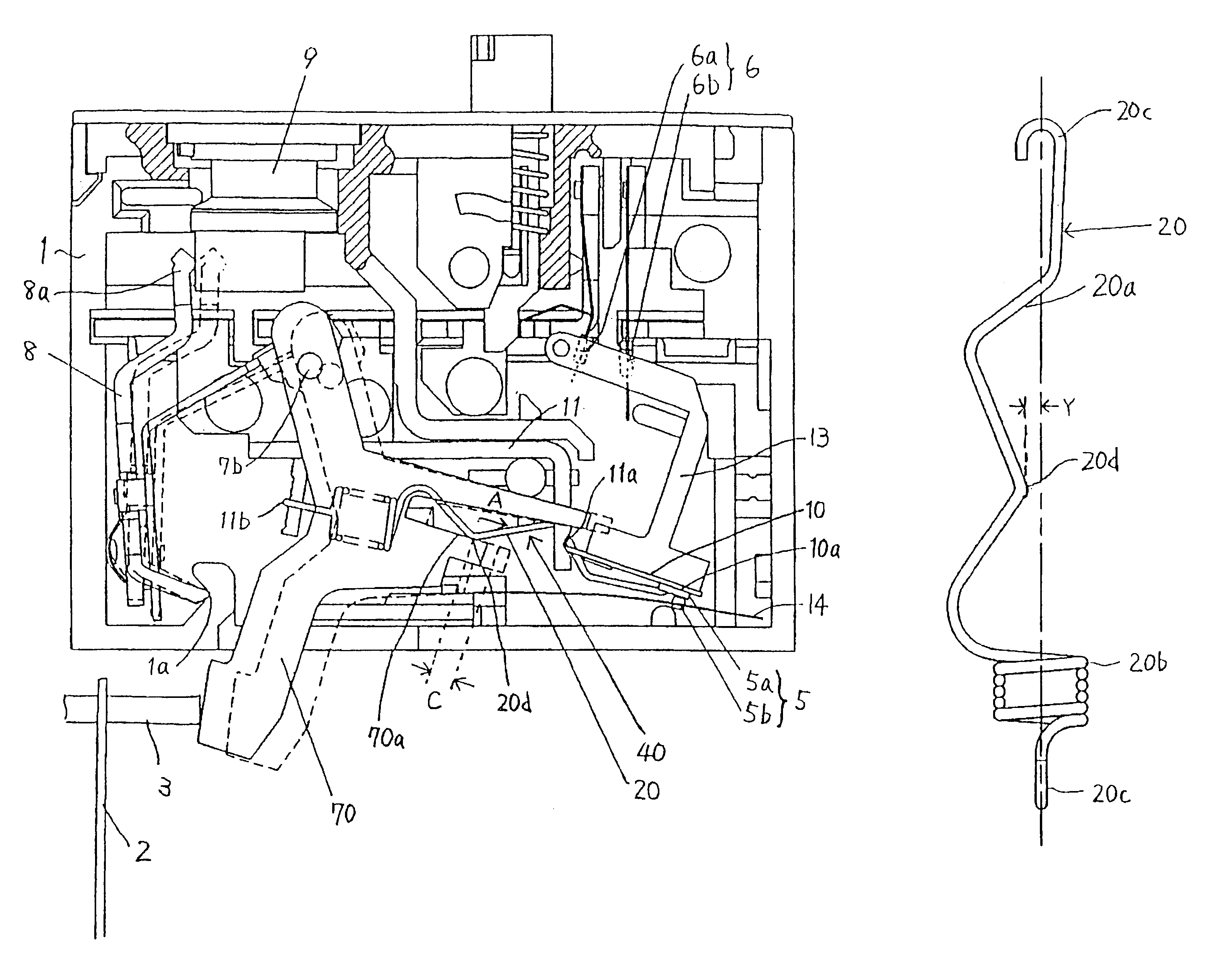
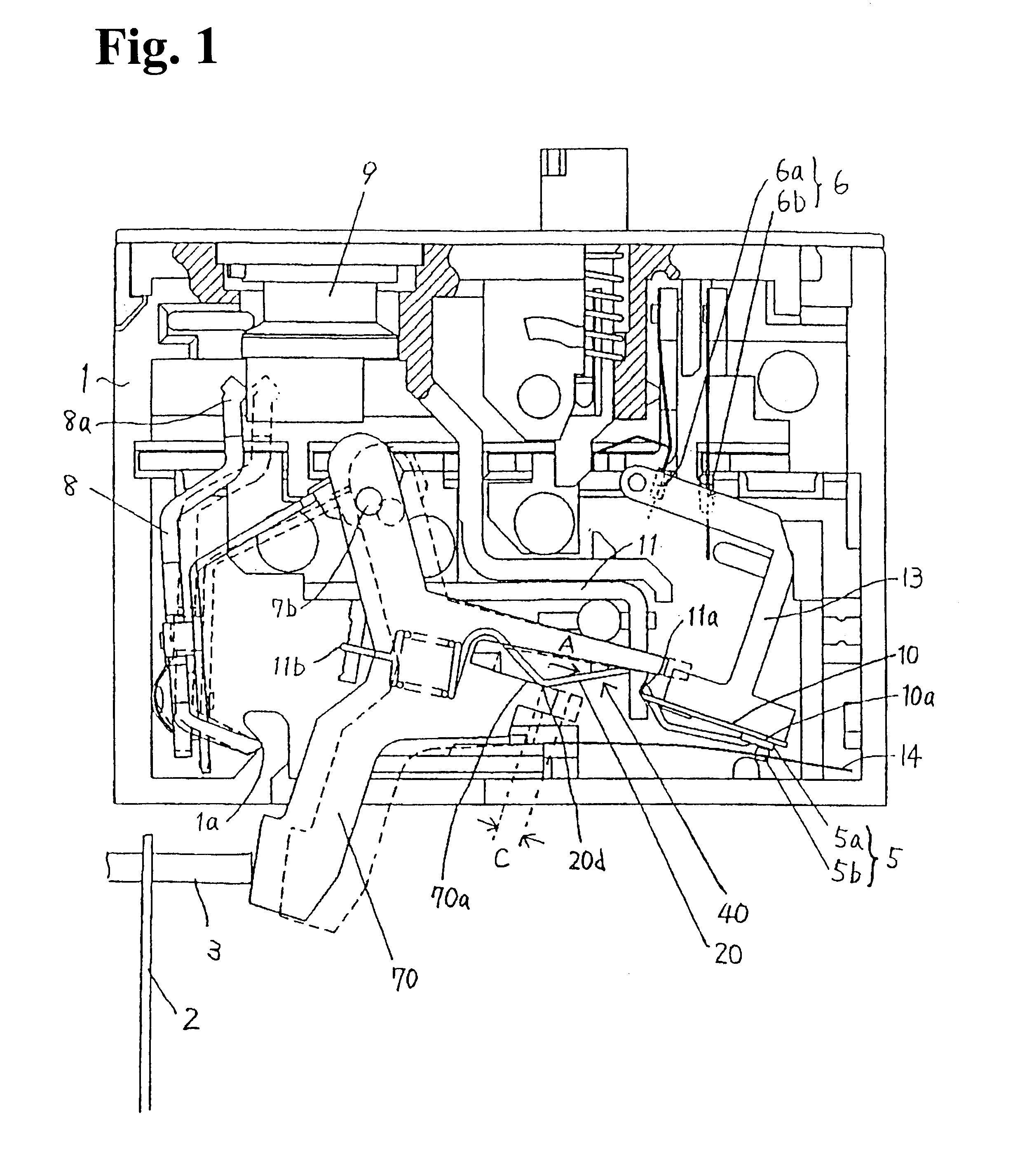
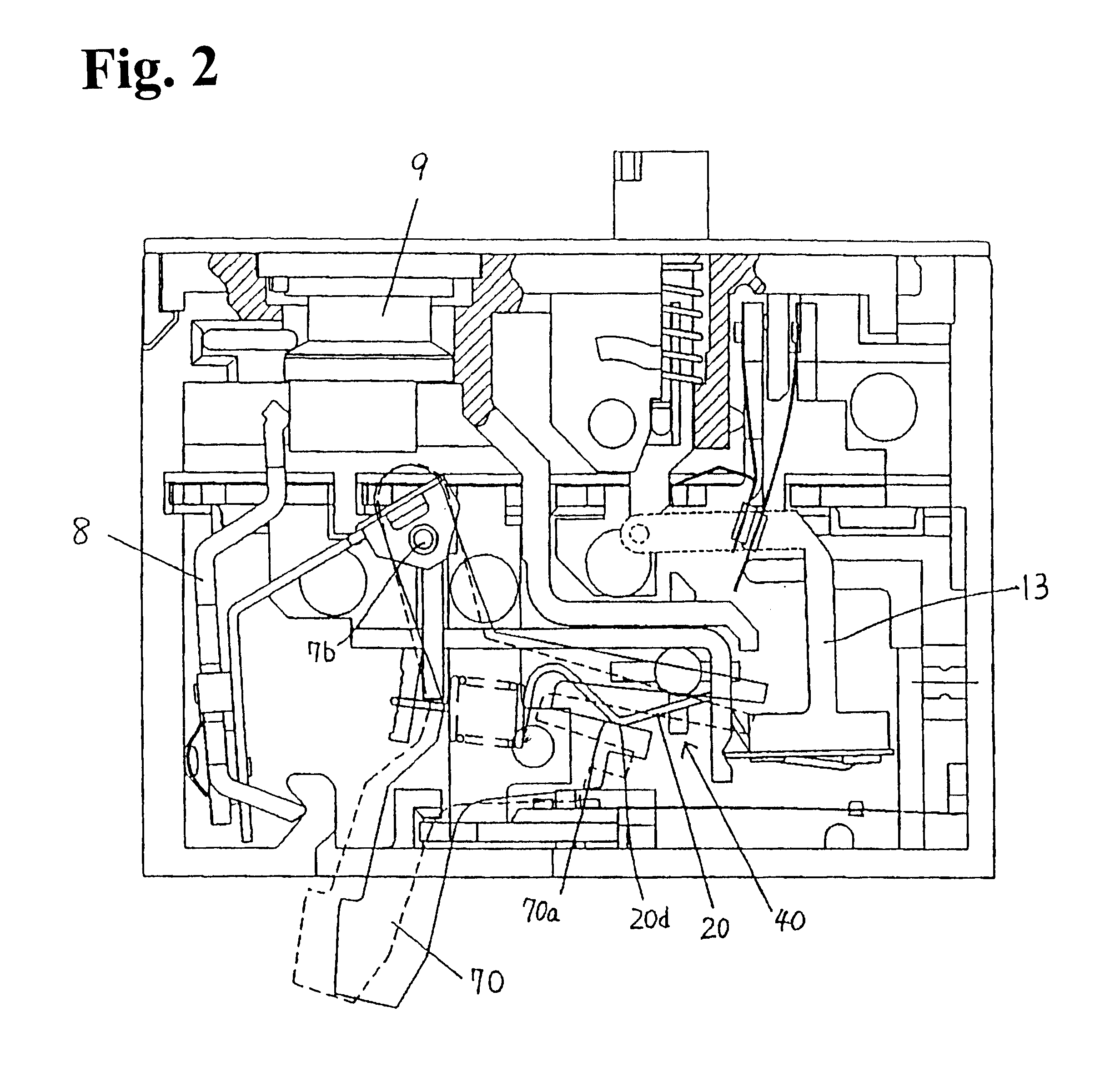
FIG. 1 is a view of an internal mechanism of a thermal overload relay showing a steady or normal state, and FIG. 2 is a view of the internal mechanism of the same relay showing an overload state. FIG. 3 is a perspective view of a tension spring, shown in FIG. 1.

The thermal overload relay according to the embodiment shown in the figures is essentially similar to the thermal overload relay shown in FIG. 4, but differs therefrom in that a tension spring 20 extending between a movable plate 10 of an inversion operation mechanism 40 and a spring catching section 11b of a support piece 11 is shaped as shown in FIG. 3, and in that a top portion of a releasing lever 70 that presses the middle of a wire of the tension spring 20 is formed to have a...


PUM


Abstract

A thermal overload relay includes an inversion operation mechanism that is driven by a releasing lever to open or close a contact. The inversion operation mechanism includes a movable plate supported at one end so as to be inverted, and a tension spring for driving the movable plate for inversion. The releasing lever presses a middle of a wire of the tension spring to drive the movable plate for inversion. A projection is formed in the middle of the wire of the tension spring to contact with the releasing lever. Thus, a stable inversion operation can be made regardless of the positioning of an adjustment dial.

Description

BACKGROUND OF THE INVENTION AND RELATED ART STATEMENTThe present invention relates to a thermal overload relay for use in combination with an electromagnetic contactor, and in particular, to an inversion structure for stabilizing an inversion operation performed by the thermal overload relay.To protect an electric motor from an overload, there is employed, as a standard distribution method, a method of combining a thermal overload relay with an electromagnetic contactor connected to a power circuit for the electric motor and allowing the electromagnetic contactor to cut of f current in an overload operation to stop the electric motor.FIGS. 4 and 5 show a conventional thermal overload relay. FIG. 4 is a view of an internal mechanism of the thermal overload relay showing a steady or general state, and FIG. 5 is a view of the internal mechanism of the thermal overload relay showing an overload state.In these figures, 1 is a main body case, 2 is a main bimetal (only one phase of a three...

Claims


Application Information

Patent Timeline
IPC IPC(8): H01H71/00H01H71/74H01H5/00H01H5/06H01H83/00H01H71/46H01H71/12H01H83/22H01H37/02H01H61/01
CPCH01H61/02H01H71/7427H01H5/06H01H71/46H01H83/223H01H2071/7454H01H37/02
Inventor FURUHATA, YUKINARIOHGAMI, TOSHIKATSUMORISHITA, FUMIHIROFUKAYA, NAOKIOKUTSU, TERUHISA
Owner FUJI ELECTRIC FA COMPONENTS & SYST CO LTD
Why Eureka
Try Eureka