Grommet and method for fixing said grommet to a panel

a grommet and panel technology, applied in the direction of electrical apparatus construction details, insulation bodies, transportation and packaging, etc., can solve the problems of inferior water stopping performance, difficult to provide sufficient space for receiving the grommet, and inability to easily perform the insertion of the gromm

Inactive Publication Date: 2002-10-15
SUMITOMO WIRING SYST LTD
View PDF8 Cites 20 Cited by
  • Summary
  • Abstract
  • Description
  • Claims
  • Application Information

AI Technical Summary

Problems solved by technology

As described above, in mounting the grommet 1 onto a vehicle body panel 2, first, the entire grommet 1 is pushed into the passenger compartment from the engine compartment side, in which case it has become difficult to provide sufficient space for receiving the grommet which has been pushed into the passenger compartment.
In such a case, however, because the small diameter tubular part side A of the recess 1c is formed into a thick wall, intensive resistive forces act when passing the grommet through the through hole 3, and the insertion of the grommet cannot be easily performed.
Furthermore, with the above method, as shown in FIG. 7, there is a tendency for a gap C to be formed between the wall surface 1c-1 on the front side of the recess 1c and the panel 2, which results in inferior water stopping performance.

Method used


Image

  • Grommet and method for fixing said grommet to a panel
  • Grommet and method for fixing said grommet to a panel
  • Grommet and method for fixing said grommet to a panel

Examples


Embodiment Construction

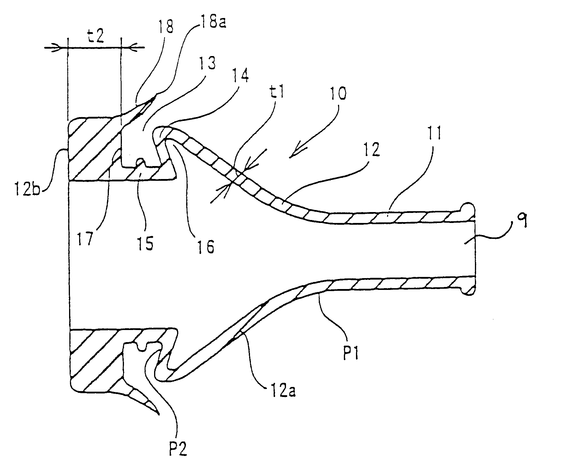
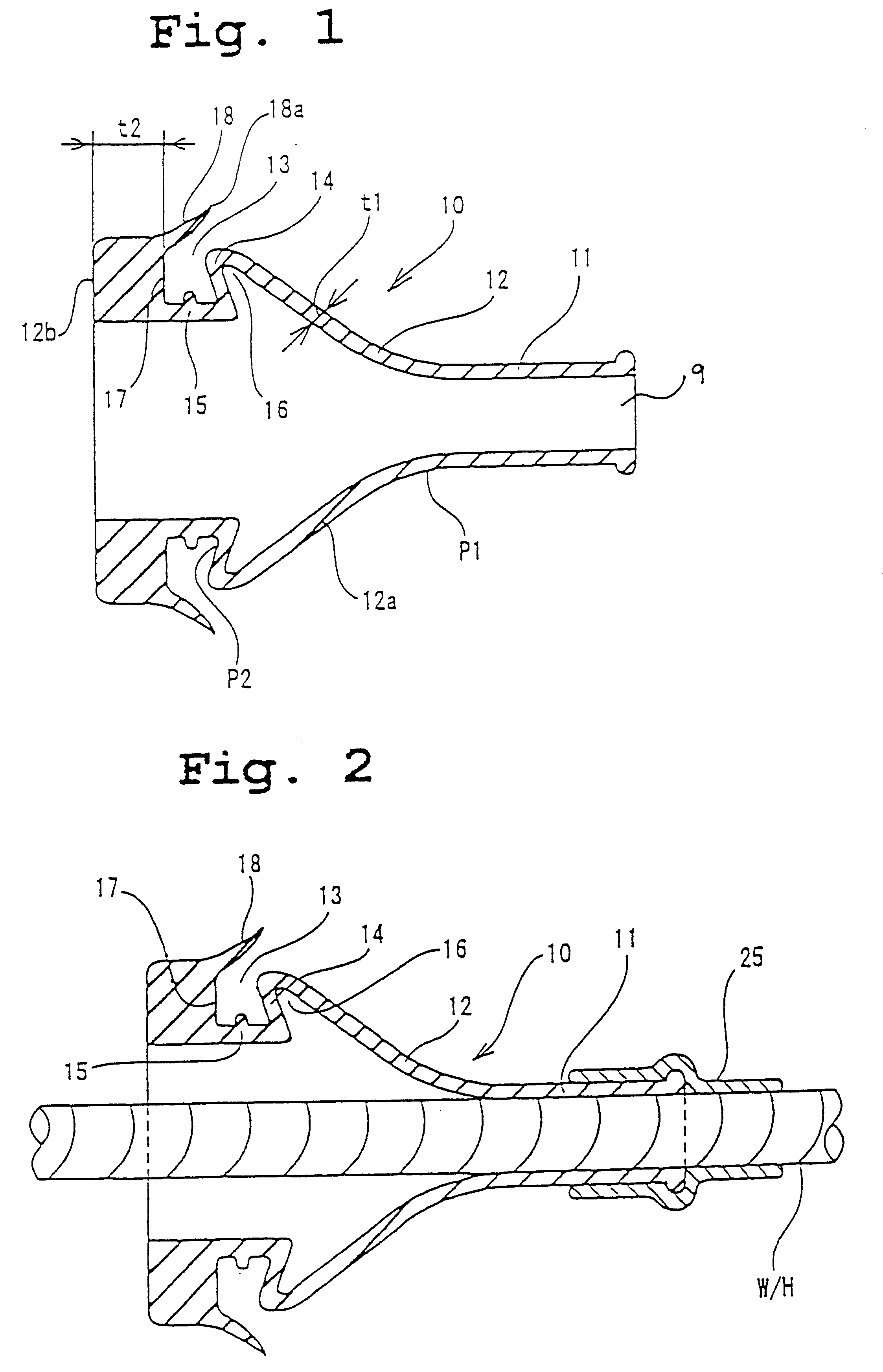
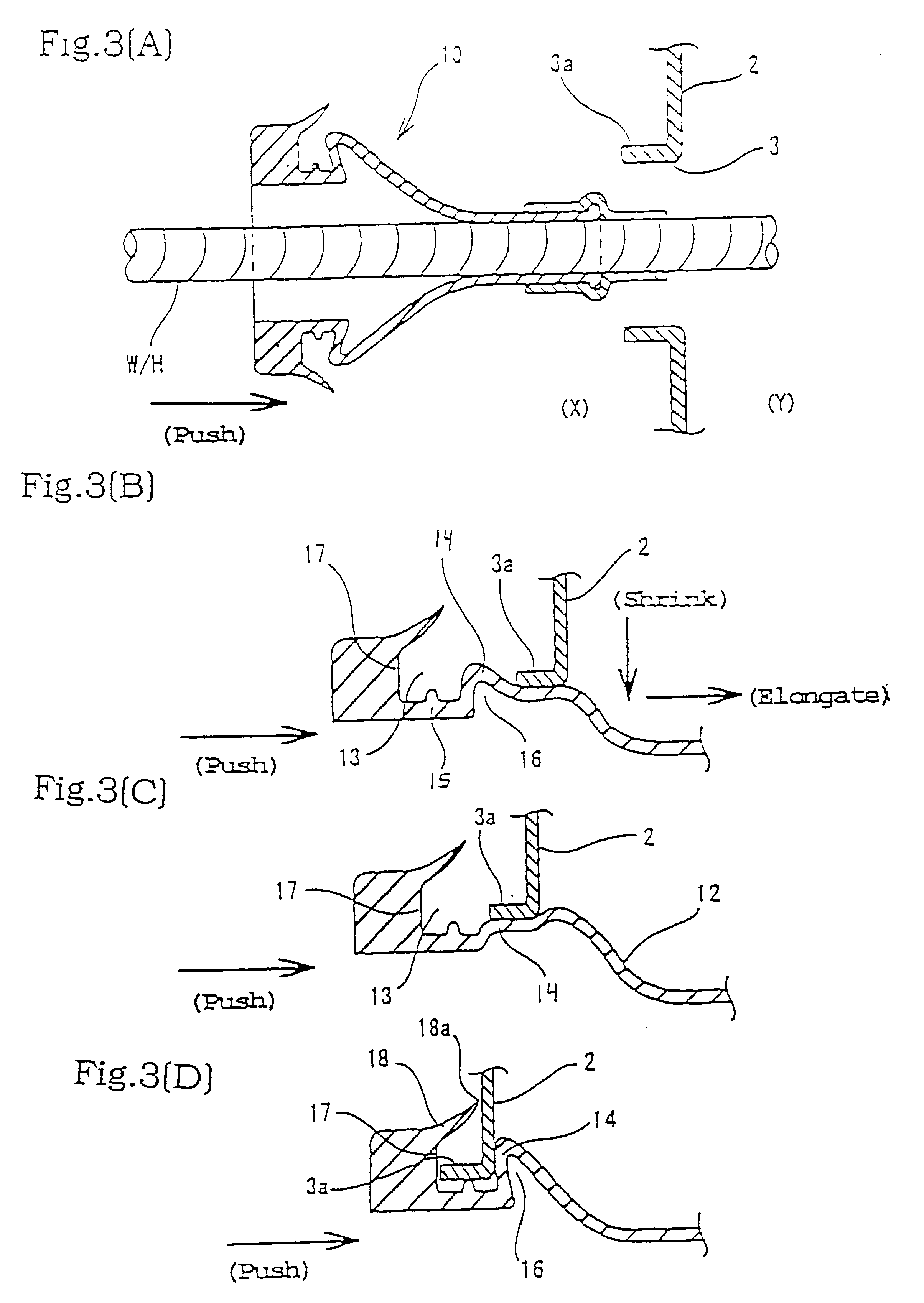
FIGS. 1 through 3 show a first embodiment of the present invention, in which a grommet 10 is formed from any suitable material, for example, of rubber or elastomer. The grommet 10 includes a small diameter tubular part 11 to tightly receive a wire harness W / H when inserted therein, an enlarged diameter part 12 that continues from an end of the small diameter tubular part 11 into a generally conical tubular shape, and a generally annular vehicle body engaging recess 13 on the outer peripheral face of the enlarged diameter tubular part 12.

The wall thickness of the enlarged diameter tubular part 12 has approximately the same thin wall thickness t1 from the position P1 of the continuation with the small diameter tubular part 11 to the bottom face end P2 of the first side wall 14 of the enlarged diameter tubular part of the vehicle body engaging recess 13 through the enlarged diameter inclined part 12a. Furthermore, the first side wall 14 is formed to have a turned-back position, from th...


PUM

PropertyMeasurementUnit
diameteraaaaaaaaaa
thicknessaaaaaaaaaa
recessed areaaaaaaaaaaa

Abstract

A grommet is provided that can be engaged in a through hole of the vehicle body panel by a single motion of pushing the grommet in only one direction. The grommet has a small diameter tubular part to tightly engage a wire harness inserted therein, an enlarged diameter part that continues from an end of the small diameter tubular part into the conical tubular shape, and a generally annular vehicle body engaging recess on the outer peripheral face of the enlarged diameter tubular part. The wall thickness of the enlarged diameter tubular part is approximately the same from the position of continuation with the small diameter tubular part to a bottom end of a first side wall of the vehicle body engaging recess. The first side wall is formed to have a turned-back portion from a tip of an inclined part that continues from the conical tubular shape to the bottom end to provide a space at the back face of the first side wall and an inclined part having an inclination is formed from a bottom face of the recess extending toward a second side wall of the recess. A thick wall forms a second side wall portion and a front end face of the enlarged diameter tubular part, and a lip projects from the second side wall toward the first side wall.

Description

1. Field of the InventionThe present invention relates to a grommet to be mounted on the wire harness for an automotive vehicle for fitting to a through hole of a vehicle body panel, and to a method for mounting the grommet onto a panel.2. Discussion of Background InformationConventionally, in laying the wire harness from the engine compartment into a passenger compartment, a grommet 1 of rubber or elastomer has been provided on the wire harness W / H, as shown in FIG. 4 and FIG. 5. The wire harness W / H is provided with the grommet 1 and is inserted into the through hole 3 of a vehicle body panel 2 separating the engine compartment (X) and the passenger compartment (Y). The grommet 1 is inserted into the periphery of the through hole 3, and is passed from the engine compartment side to the passenger compartment side through the through hole 3 and is positioned therein to prevent water or dust from entering into the passenger compartment from the engine compartment sideThe grommet 1 ha...

Claims


Application Information

Patent Timeline
Patent Type & Authority Patents(United States)
IPC IPC(8): B60R16/02H02G15/00H02G3/08H02G15/013H05K7/00H01B17/58H02G3/22
CPCB60R16/0222H02G3/083H02G15/013
Inventor KONDOH, TATSUYASAKATA, TSUTOMUHATTORI, YUKIMITSU
Owner SUMITOMO WIRING SYST LTD
Why Eureka
Try Eureka