Impression tray device with removable segments for dental implant transfers

Inactive Publication Date: 2002-10-22
GUILLAUME +1
View PDF8 Cites 21 Cited by
  • Summary
  • Abstract
  • Description
  • Claims
  • Application Information

AI Technical Summary

Problems solved by technology

The optionally-perforated conventional impression trays which are used with conjoined or adjoined prostheses cannot be adapted to taking impressions of transfers since they do not have an opening giving access to the screw of the transfer so as to allow the implant to be released, thus enabling the impression to be withdrawn.

Method used


Image

  • Impression tray device with removable segments for dental implant transfers
  • Impression tray device with removable segments for dental implant transfers
  • Impression tray device with removable segments for dental implant transfers

Examples


Embodiment Construction

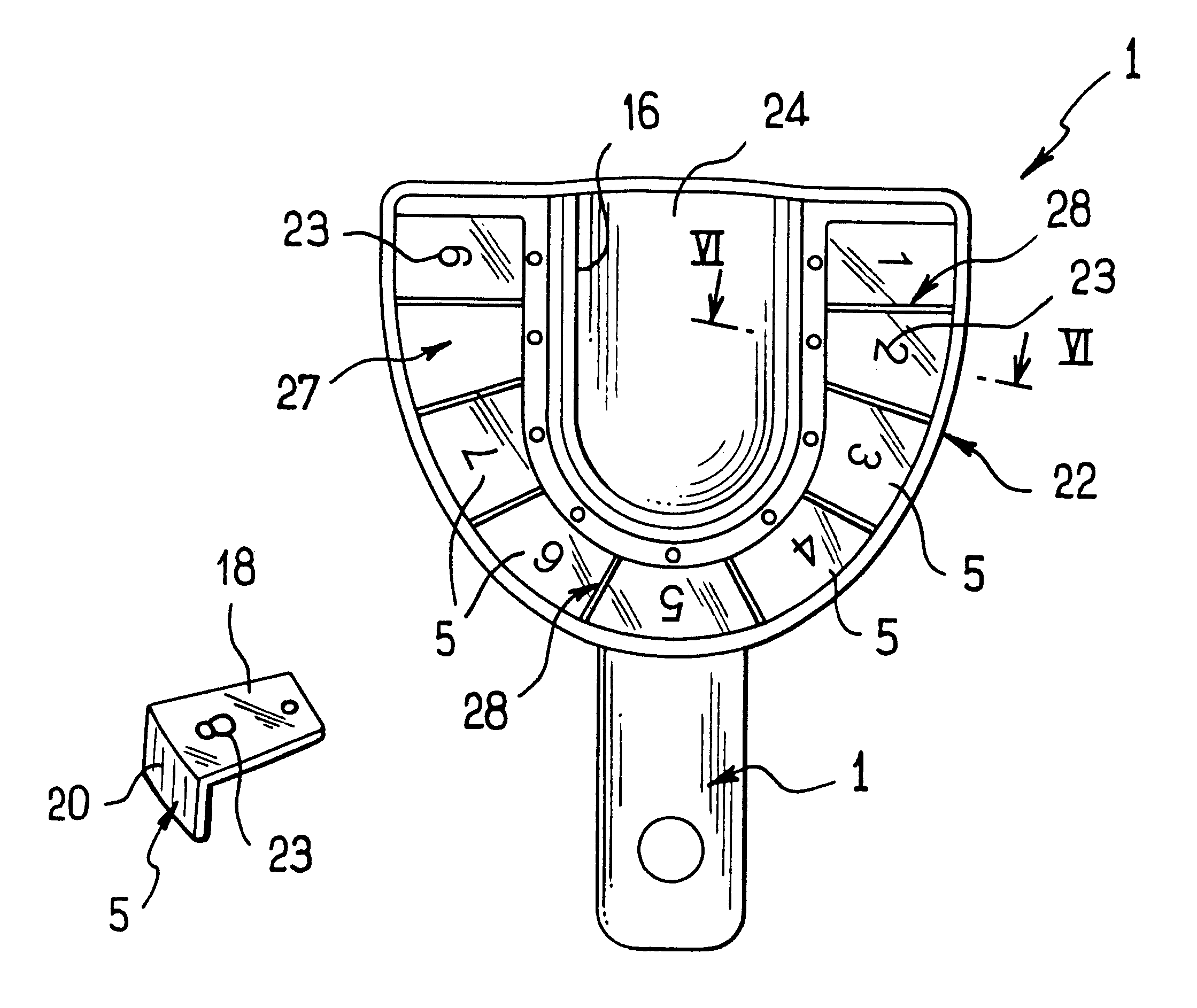
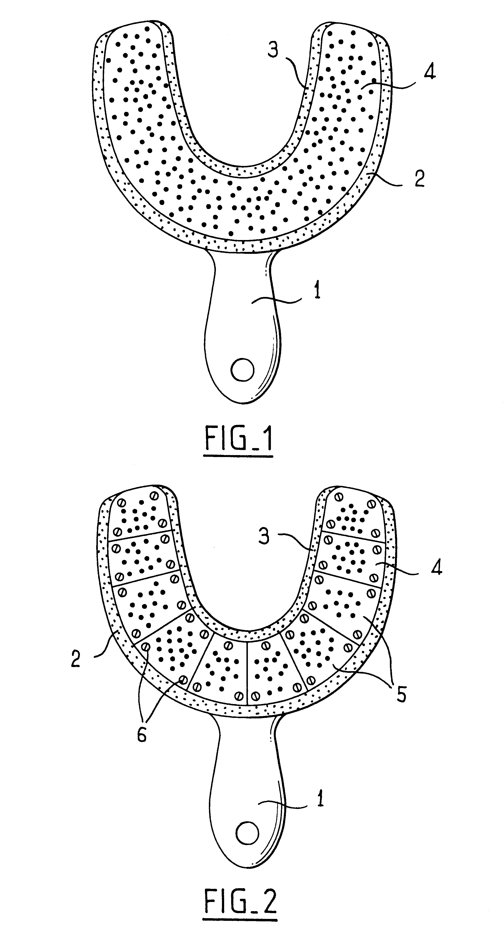
FIG. 1 shows that the impression tray 1 is a semi-elliptical trough having an outer or vestibular face 2, an inner face 3 adjacent to the tongue or the palate, and a closed face 4 corresponding to the grinding surface of the teeth. This impression tray is filled with soft impression material and placed on the dental arch until the material sets.

FIG. 2 shows that in accordance with the invention, the impression tray 1 has a succession of removable segments 5 in its closed face 4 which are secured to the tray 1, in this case by screws 6. One or more of the removable segments 5 can be withdrawn as a function of requirements by loosening the screws 6.

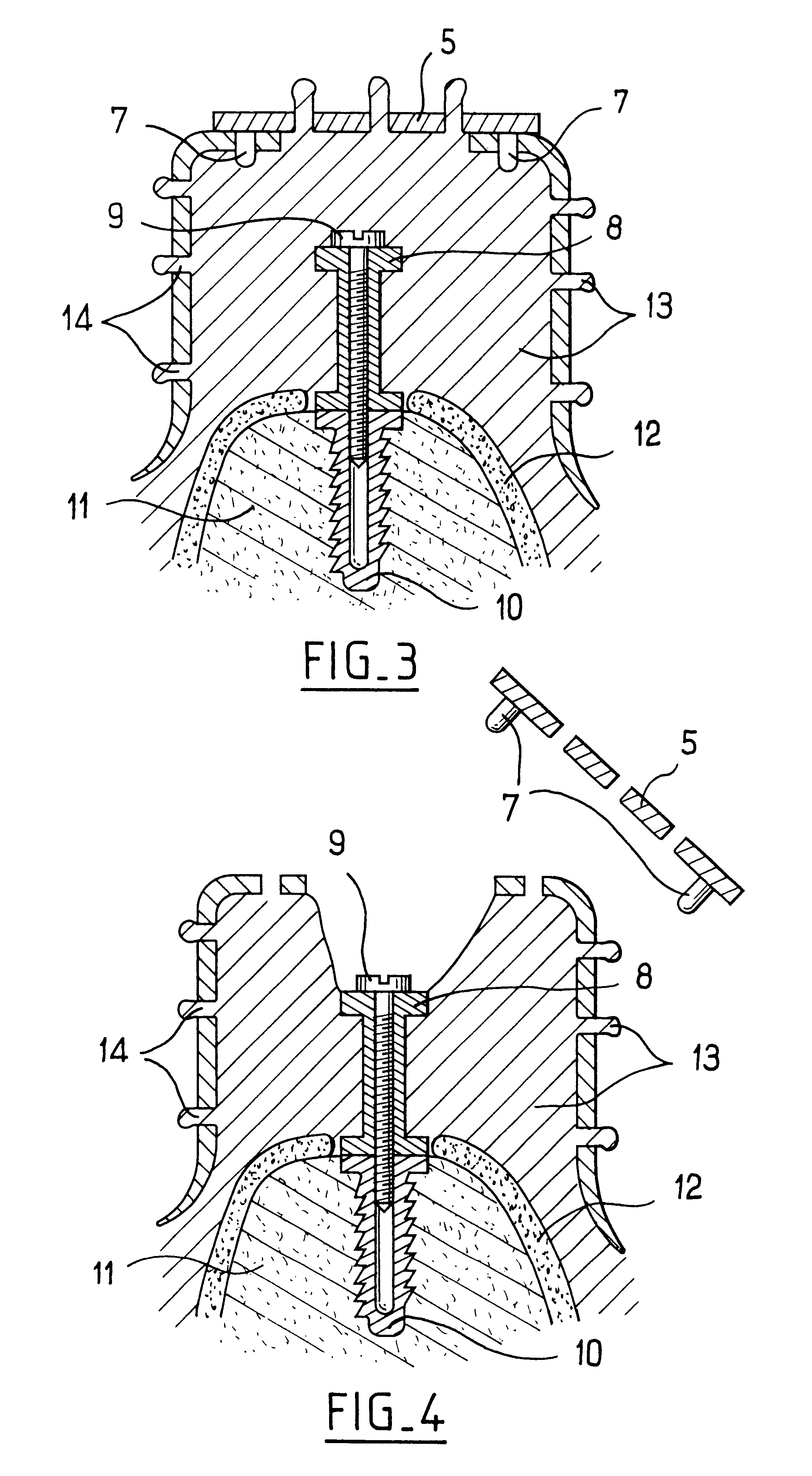
FIG. 3 is a cross-section through the device of the invention. In this embodiment, the removable segments 5 are secured to the tray 1 by studs 7. The section plane contains the axis of the studs 7, the axis of the transfer 8, the axis of the screw 9 which secures the transfer 8 to the implant 10, and finally the axis of the implant 10 situa...


PUM


Abstract

An impression tray for taking impressions of transfers of dental implants comprises, in its closed face, a succession of removable segments secured by screws or by studs. After the impression material has set, the segment(s) giving access to the screw of the transfer is / are removed.

Description

An implant transfer is a post secured to the implant situated in the dental arch by means of a screw engaged in and tightened in the internal tapping of the implant.The optionally-perforated conventional impression trays which are used with conjoined or adjoined prostheses cannot be adapted to taking impressions of transfers since they do not have an opening giving access to the screw of the transfer so as to allow the implant to be released, thus enabling the impression to be withdrawn.OBJECTS AND SUMMARY OF THE INVENTIONThe present invention provides an impression tray device for a transfer of a dental implant, in which the tray device has a closed face which includes a succession of removable segments.The invention and its implementation will appear more clearly from the following description made with reference to the accompanying drawings showing some embodiments purely by way of example: in the drawings, the same items are identified by the same numbers.The drawings include th...

Claims


Application Information

Patent Timeline
Patent Type & Authority Patents(United States)
IPC IPC(8): A61C8/00A61C9/00
CPCA61C8/0001A61C9/0006
Inventor GUILLAUMEMAZEIRAT, JEAN
Owner GUILLAUME
Why Eureka
Try Eureka