Patch antenna array with isolated elements

a technology of antenna array and isolated elements, applied in the field of antenna devices, can solve the problems of horizontal pattern degradation and thereby the degrading of communication quality as a whol

Inactive Publication Date: 2002-10-29
MITSUBISHI ELECTRIC CORP
View PDF5 Cites 31 Cited by
  • Summary
  • Abstract
  • Description
  • Claims
  • Application Information

AI Technical Summary

Problems solved by technology

For this reason, when the gain of the cross-polarized wave is lowered, the radiation pattern in

Method used


Image

  • Patch antenna array with isolated elements
  • Patch antenna array with isolated elements
  • Patch antenna array with isolated elements

Examples


first embodiment

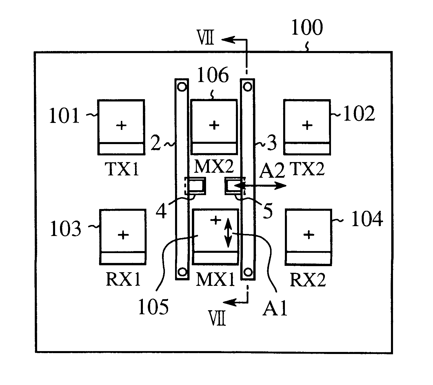
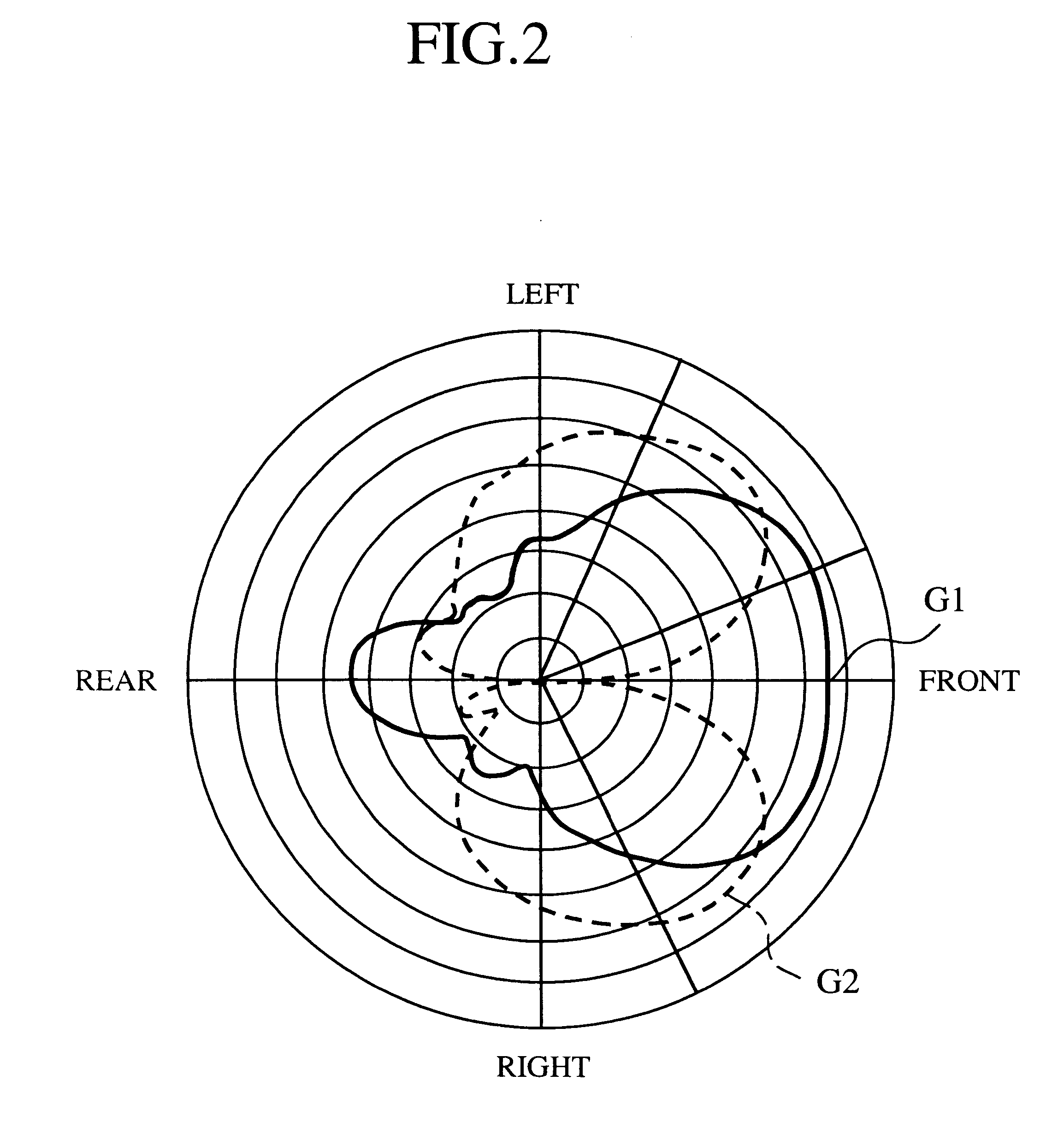
FIGS. 1A and 1B are illustrations showing an antenna device according to a first embodiment of the present invention, wherein FIG. 1A is a plain view and FIG. 1B is a side view thereof. FIG. 2 is an illustration showing the characteristic of the radiation pattern in the horizontal direction of each of the antenna elements in the antenna device shown in FIGS. 1A and 1B. Note that the word "antenna element" may be hereinafter referred to as a short patch antenna element or a short patch antenna as mentioned before, or even as a powered antenna or a powered antenna element. Within the structural elements configuring the antenna device of this first embodiment, the same reference numerals are put to the elements same or similar to those configuring the conventional antenna device, and the explanation thereabout is thus omitted here.

In these figures, reference numeral 2 denotes an element to which no power is fed (hereinafter referred to just as a non-powered element), and is disposed be...

second embodiment

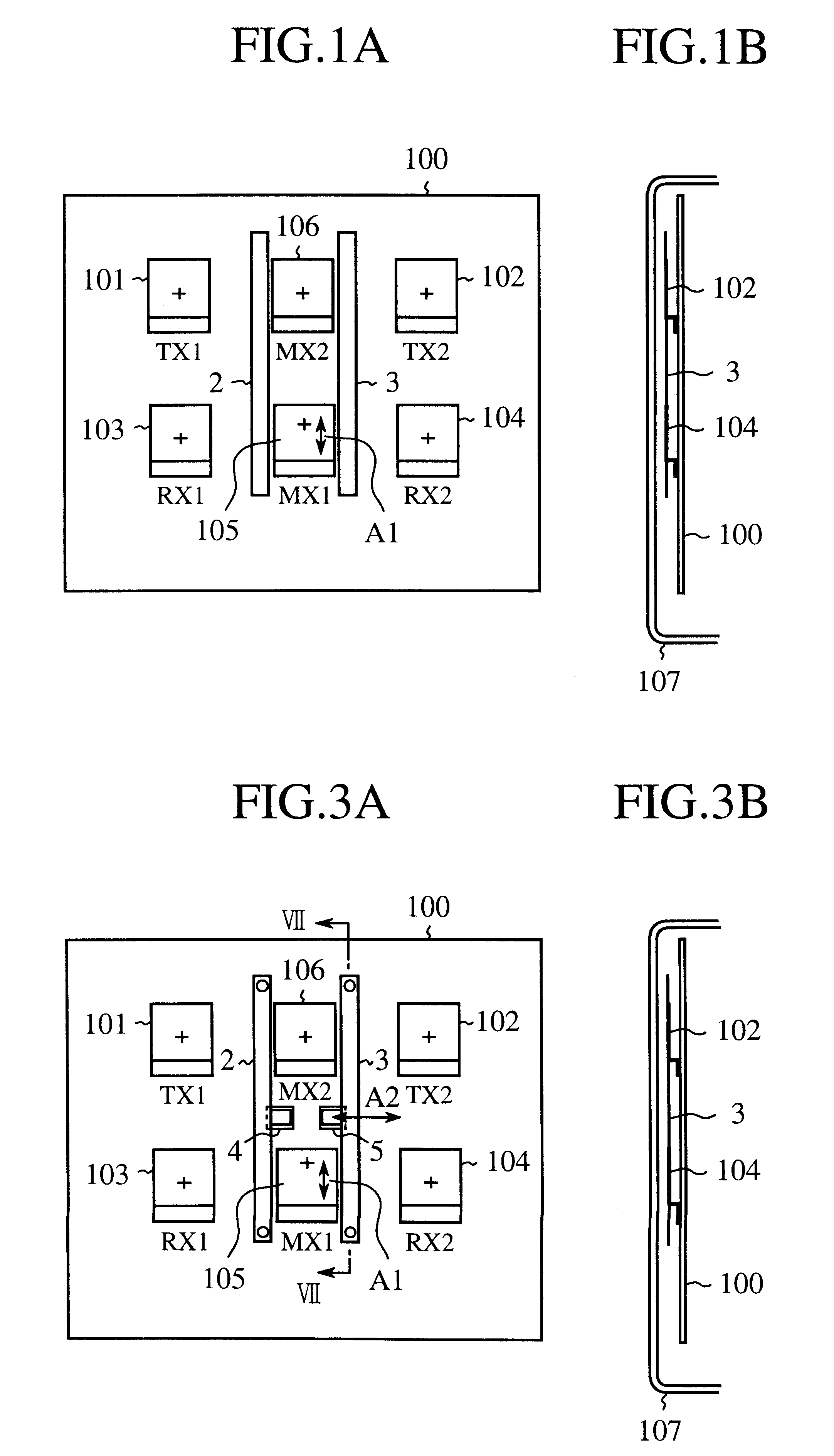
FIGS. 3A and 3B are illustrations showing an antenna device according to a second embodiment of the present invention, wherein FIG. 3A is a plan view and FIG. 3B is a side view thereof. FIG. 4 is a plain view showing the magnified non-powered element shown in FIG. 3A. FIG. 5 is a plain view showing the magnified metal fixing portion shown in FIG. 4. FIG. 6 is a sectional view showing the configuration of the metal fixing portion shown in FIG. 4 when mounted on the ground plate 100. FIG. 7 is a sectional view observed from the line cut along VII--VII of FIG. 3A, and FIG. 8 is an illustration showing the characteristic of the radiation patterns in the horizontal direction of each of the short patch antennas in the antenna device of FIGS. 3A and 3B. Within the elements configuring the antenna device of this second embodiment, the same reference numerals are put to the elements same or similar to those configuring the conventional antenna device of the first embodiment, and the explanat...


PUM


Abstract

On the ground plate uprightly mounted in the vertical direction, a plurality of short patch antennas are provided at mutually adjacent positions, and also a pair of non-powered elements are mounted, wherein each of the non-powered elements is disposed between the plurality of short patch antenna elements in such a manner as to extend in the vertical direction and is electrically insulated from the ground plate. Due to this construction, the radiation pattern in the horizontal direction of the plurality of short patch antennas can be greatly improved.

Description

1. Field of the InventionThe present invention relates to an antenna device for use in an indoor type radio station.2. Description of the Related ArtFIGS. 9A and 9B are illustrations showing the positional configuration of a plurality of short patch antennas mounted in a conventional antenna device, wherein FIG. 9A is a front view and FIG. 9B is a side view. FIGS. 10A and 10B are magnified views respectively of the antenna device of FIG. 9A and FIG. 9B showing one of the short patch antennas mounted therein, wherein FIG. 10A is a sectional view observed from the line cut along I--I of FIG. 9A, and FIG. 10B is a plain view of that short patch antenna. FIG. 11 is a block diagram showing a configuration of the conventional antenna device, and FIG. 12 is an illustration showing the characteristic of the radiation patterns of one of the short patch antennas (each of which may be referred to as an antenna element hereinafter) in the conventional antenna device. Further, FIG. 13 is an illu...

Claims


Application Information

Patent Timeline
IPC IPC(8): H01Q21/28H01Q9/04H01Q19/00H01Q21/00H01Q21/08H01Q1/52H01Q13/08
CPCH01Q9/0421H01Q19/005H01Q21/28
Inventor NAKAMURA, KIYOSHIGE
Owner MITSUBISHI ELECTRIC CORP
Why Eureka
Try Eureka