Automotive air conditioning unit

a technology for air conditioners and motor vehicles, applied in the direction of defrosting, domestic cooling devices, applications, etc., can solve the problems of pressure drop, and lowering the performance of the sam

Inactive Publication Date: 2002-11-12
CALSONIC KANSEI CORP
View PDF13 Cites 27 Cited by
  • Summary
  • Abstract
  • Description
  • Claims
  • Application Information

AI Technical Summary

Problems solved by technology

The uneven pressure distribution brings about uneven air flow throughout the air passing area of the evaporator 1 and thus lowers the performance of the same.
That is, due to unbalanced air flow rate between larger and smaller areas of the triangular air inlet opening 4 and unbalanced air flow resistance in the triangular space between one side facing the larger area of the inlet opening 4 and the other side facing the smaller area of the same, there is produced an air swirl "S" at a central portion of the space which causes a pressure drop at such portion.
As is seen from this graph, increased air flow appears around an area from the position "B" to the position "C" and around the position "D" and poor air flow appears at the other areas, which causes an uneven air flow through the evaporator 1 and thus lowers the performance of the same.
However, due to generation of the air swirl "S" in the space, the water:drops or water is not smoothly drained to the engine room through the drain pipe 9.
This may bring about a trouble of the electric blower in the air intake unit.

Method used


Image

  • Automotive air conditioning unit
  • Automotive air conditioning unit
  • Automotive air conditioning unit

Examples


first embodiment

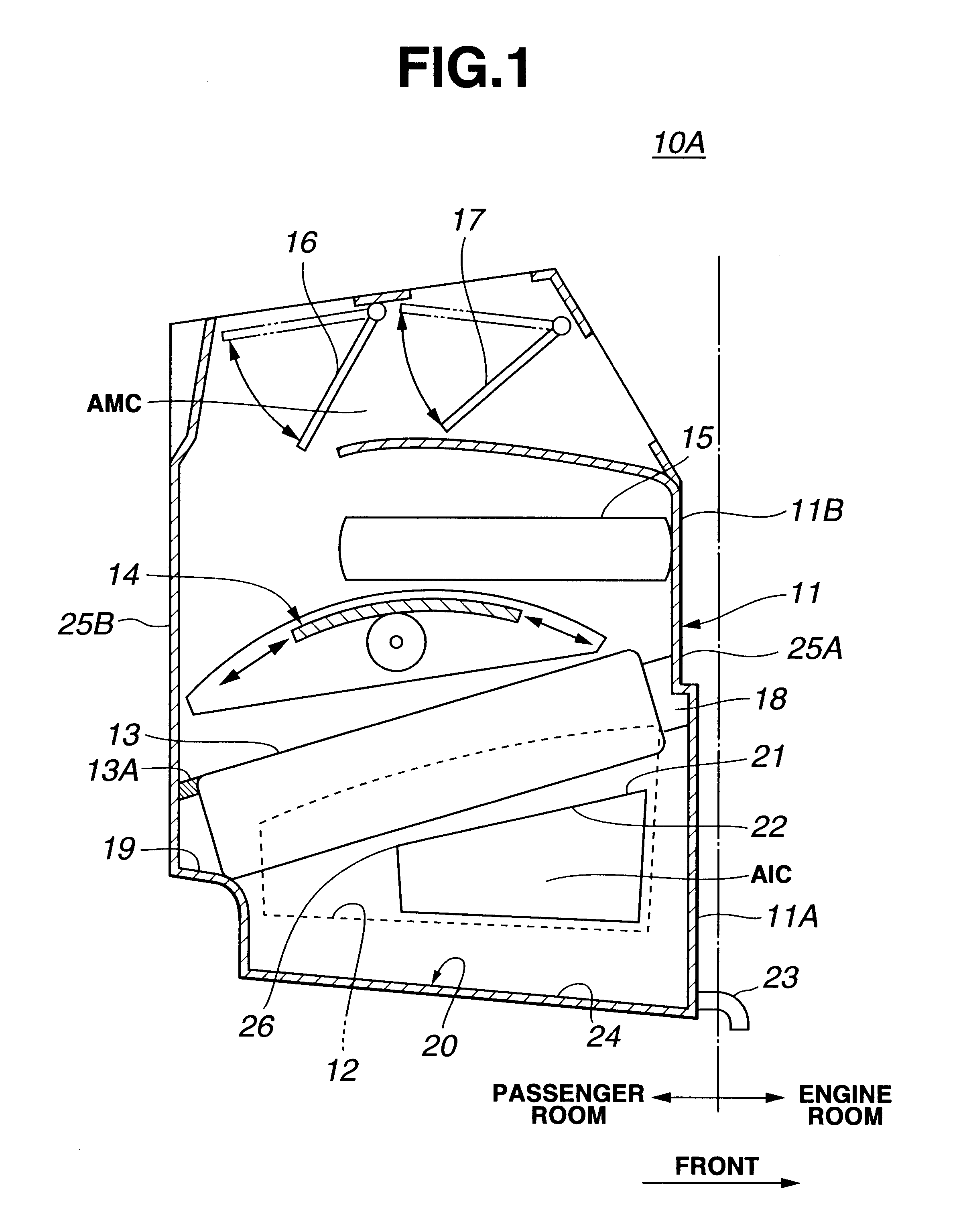
Referring to FIGS. 1 to 6 of the drawings, there is shown an automotive air conditioning unit 10A which is the present invention.

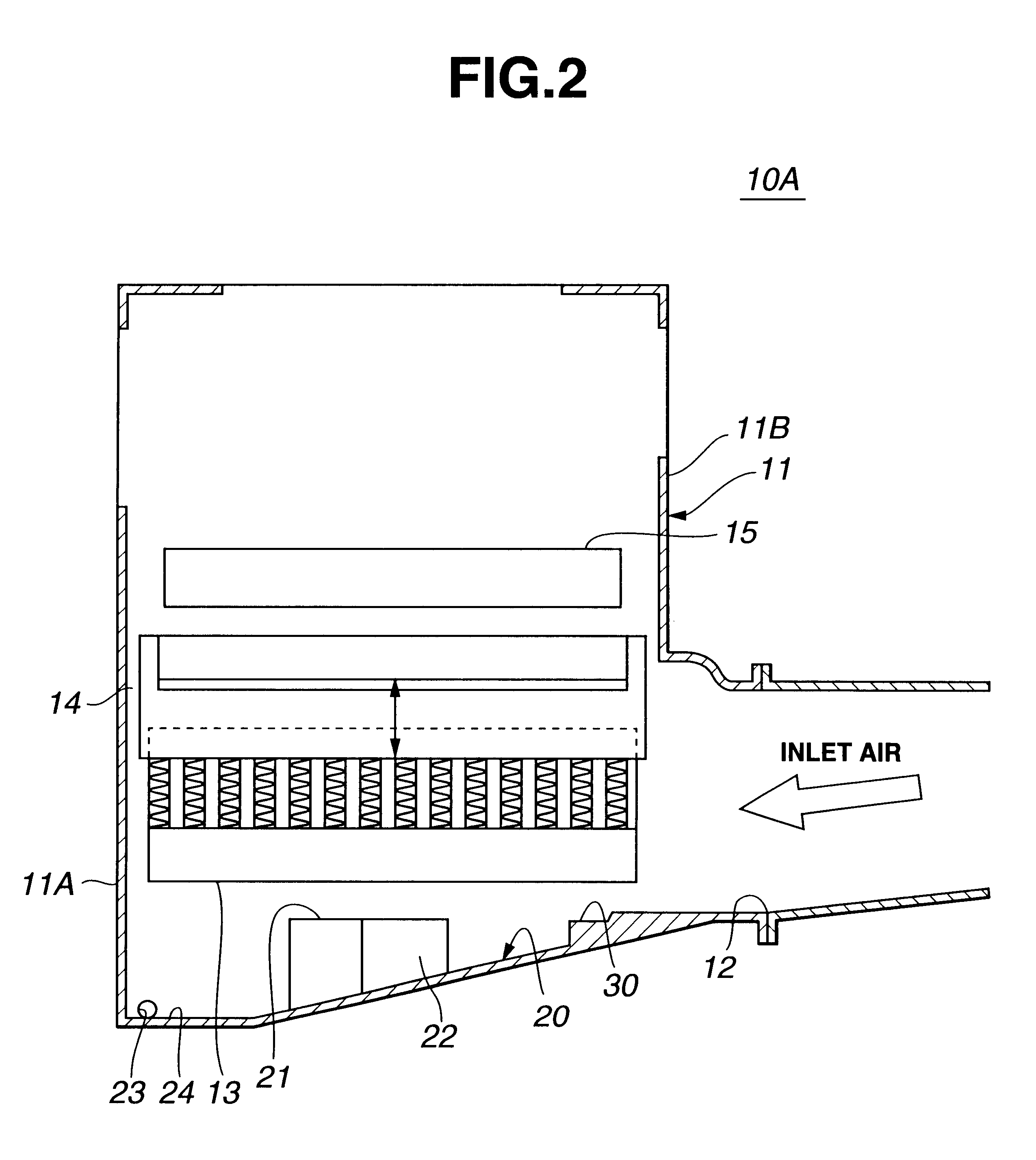
As is well shown in FIGS. 1 and 2, the air conditioning unit 10A comprises a casing 11 which includes a lower half part 11A and an upper half part 11B which are detachably connected.

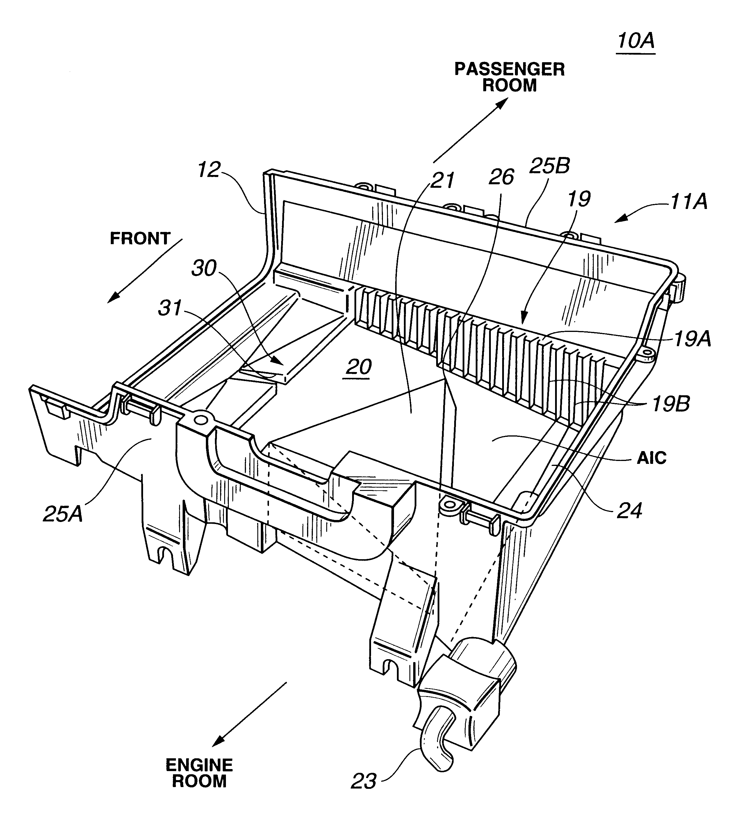
FIG. 3 shows a perspective view of the lower half part 11A of the casing 11. FIG. 4 is a plan view of the lower half part 11A. As is best understood from these drawings, the lower half part 11A is formed at its right side wall with an air inlet opening 12 through which air brown by an electric blower (not shown) installed in an air intake unit (not shown) is led into the lower half part 11A.

As is best shown in FIG. 1, an evaporator 13 is installed in a lower portion of the casing 11, which is inclined with its front portion raised. A rounded slide door 14 is arranged above the evaporator 13, which serves as an air mix door. A heater 15 is arranged above the slide door 14. At a ...

second embodiment

Referring to FIGS. 7, there is shown an automotive air conditioning unit 10B which is the present invention.

embodiment 10b

Since this embodiment 10B is. similar in construction to the above-mentioned first embodiment 10A, only a portion different from that of the first embodiment 10A will be described in the following.

That is, in this second embodiment 10B, a plurality of slits 19B (see FIG. 3) defined by the stepped portion 19 of the lower half part 11A of the casing 11 are used to flow down the condensed water drops on the upper surface of the evaporator 13 toward the bottom surface 20 of the casing 11. That is, any water drops or water gathering on the step 19A of the stepped portion 19 can flow down to the air inlet chamber "AIC" through the slits 19B.


PUM


Abstract

An air conditioning unit is provided comprising a casing including an air flow passage, an evaporator and a heater arranged in the air flow passage, and an air flow control door for controlling an air amount flowing in a heater-passing passage. A water guide groove is provided at a bottom surface of the casing with a slanted bottom. A triangular projection is formed on the bottom surface of the casing, the triangular projection being oriented so that one apex of the projection is directed toward the front wall of the casing.

Description

1. Field of the InventionThe present invention relates in general to an automotive air conditioner, and more particularly to an automotive air conditioning unit which comprises generally a casing defining therein an air passage with air inlet and outlet openings, an evaporator installed in an upstream portion of the air passage and a heater installed in a downstream portion of the air passage, an air intake unit connected to the air inlet opening of the air passage and an electric blower installed in the air intake unit for producing an air flow directed toward the air outlet opening through the air passage.2. Description of Prior ArtIn order to clarify the task of the present invention, two known automotive air conditioning units will be described with reference to FIGS. 21 and 22 of the accompanying drawings.In FIG. 21, one known automotive air conditioning unit 3 is shown, which is constructed compact in size for providing front passengers with a larger foot space. The unit 3 gen...

Claims


Application Information

Patent Timeline
Patent Type & Authority Patents(United States)
IPC IPC(8): B60H1/00B60H1/32
CPCB60H1/00514B60H1/3233
Inventor NANBA, YOSHIAKITAKASAKI, MORIHIROSAWANO, KENICHIROKATO, OSAMUNODA, YOSHITOSHI
Owner CALSONIC KANSEI CORP
Why Eureka
Try Eureka